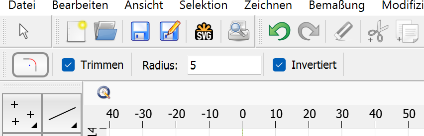
Hello,
i do not see the polyline mode in the “round” modificator as you see in the screenshot below.
I have to activate this mode in the QCAD3.ini file. Am i doing something wrong or do i have to activate some sort of extended options mode?
Polyline mode for the rounding tool is a highly experimental feature and might or might not work for your polylines. It cannot be easily enabled since it will very likely not work for some or even most of your polylines and we do not accept bug reports for experimental features.
Ah ok thank you for the information. I just thought it has to be normally available because i have seen the option in the GUI in this post from Husky: Polyline mode to round all corners of a polyline - QCAD Professional / QCAD Suggestions and Feedback - QCAD Forum
EDIT: This post has incorrect instructions!! Please jump over it!
Just if anybody want to use this experimental feature and want to turn it ON and OFF in the gui rather than in the config file you may use the following shell commands:
Get the current status of PolylineMode:
RSettings.getValue("RoundPro/PolylineMode", "default");
Set the PolylineMode to ON:
RSettings.setValue("RoundPro/PolylineMode", "true");
Set PolylineMode to OFF:
RSettings.setValue("RoundPro/PolylineMode", "false");
Hi,
I would flag your tweak as incomplete or even as not appropriate.
The real method is to activate the experimental feature in full.
Setting “RoundPro/Experimental” to true/false.
All because your tweak doesn’t handle the Options Toolbar widgets initialization as required.
You can’t opt out with a checkbox for only adapting an indicated corner for example.
It relies on the resource RPolyline.roundAllCorners(radius).
Look that up on the forum and you might find out why it is disabled as being buggy.
Typically when bulging segments are involved.
But also when the radius is too large for some/all polyline segments.
Even a well designed tool that I wrote for that may fail in some situations.
The difference is that it reports/indicates the offending corner(s) and lists a reason why.
I can then try to fix the situation.
There are mathematical cases that can’t be solved.
It all start with how an Arc is merged to a polyline.
One of the endpoints its exact position is discarded when almost connected …
… But the sweep is converted to a bulge factor as is.
The reverse conversion is not the same Arc and that may intersect at a different place than at the original corner or may even not intersect with the intended segment at all.
Regards,
CVH
Hi,
thank you for your hint with:
Setting “RoundPro/Experimental” to true/false.
This is basically what i have searched for the whole time! I added the Experimental=true line to the RoundPro section in the qcad3.ini and now i got the polylinemode and oneclick mode selectable by the gui how i have seen it in the link mentioned above.
I know it is experimental and not meant to work everytime, but i safe more time with this mode (placement of floor heating pipes) even if it produces sometimes not desired results.
Thank you!
An old advice of me concerning polylines is to trim both Line/Arc segments pair-wise before merging. And that for ever set of two connected segments.
But in the end that won’t hold in some specific cases.
Because trimming also relies on a mutual intersection point, mathematically.
Things are not or remain not the same as expected with the typical flaws, various tolerances and the number system limitations.
With that in mind, don’t overdo exploding polylines and merging them back too often.
And thus also the modification of a polyline what is in fact handled on segment base.
See it as a final stage for connected line/Arc segments.
Regards,
CVH
Ok, do i have you understand correctly, that the most problems with rounding polylines occur if there are arc and line segments included in the poly line. In my case, I have only line segments and therefore i think i have not experienced any problems with that function right?
An other exception is that QCAD can merge two Line segments that don’t really connect with inserting a (very) short bridging segment.
Rounding such a system may also produce strange results.
An interesting feature but I would avoid that.
The downside then is that straight things can be shifted slightly to make them connect.
Mostly only fractions of degrees but in my book that is incorrect.
There are several other exceptions.
The typical origin is that mathematically resources are about correct and function well for larger designs where a bit of error (play) isn’t really visible or considered as not important enough.
Again, …
… Blindly modifying a design based on arbitrary tolerances and decisions …
… Is incorrect in my book.
Like I said, my Polyline corner rounding tool doesn’t round such corners but reports what is wrong. There is no easy, unique and simple solution for all problems that may occur.
Never released because user intervention is needed to resolve issues at will.
‘Better safe than sorry’
You may indeed start with straight segments only, but after rounding all corners you have straight and bulging segments.
It now depends on if this is final or if the Polyline is modified any further.
It is a bit incorrect to speak of ‘Polylines with Arcs’ … There are no Arcs in a Polyline.
An Arc has a center, a radius and end angles.
A bulging segment has endpoints (nodes or vertices) and a bulging factor.
One can convert both forth and back but it is never utterly exact.
Already Polar to Cartesian or back and the bulge is based on tan(sweep/4).
Note that any modification involves such conversions and that an error can only increase.
Regards,
CVH
Ok i see it is pretty complex if i go in to details, even if it look pretty easy in the first place 
If you talk about your Polyline corner rounding tool, you mean the polyline mode in the round tool or do you have a own tool as a plugin for that?
By the way for my application the polyline rounding mode works perfectly. I just round it once and only if it contains only straigt lines and no bulging segments. Even if i get a slightly error (which i should not get in my case either) i do not care about it. This use case would also profit for a polyline mode in the segment trim mode to remove all bulgin segments and start again with a different radius for example. I know this also contains the same problems you talked about. Maybe i get this functionality added with a skript or so.
Thank you for the thorough explanation!
Yes, I wrote myself an Addon tool that could handle a Polyline with bulging segments.
All after that I reported that the RPolyline.roundAllCorners(radius) resource failed for those.
I am an CNC engraver, sometimes coin size things with many artistic curves.
Rounding corners is essential for keeping the FEED up in a controllable way.
But in the end one will always get stuck on ‘Mathematically good enough for most users’.
Designing in microns instead of mm solves some issues because of the larger values.
The opposite is true when designing in inches or meters for example.
Regards,
CVH
If your acceleration of the machine is not infinite, round would be better yes 
Do you have published this addon?
Already mentioned:
Regards,
CVH