Hi,
I want to be able to see the border of viewports in the model space.
When I create a viewport and draw its shape in the model space, a border is briefly drawn then QCAD asks for which layout block to add the viewport to, and the border is then gone from the model space.
I want to do this so I can see each portion of the model space used by each viewport. For example a linear structure like a road or in my case a large dam embankment wall 750m long. I want to have 3 layout block drawings A3 size at 1:1000 scale, with small overlap that cover the whole length of the dam axis. - Easily done, but I also want a 1:2500 scale overall layout block plan that shows the entire length, with a border around the contents of each of the 3 A3 1:1000 layouts to aid navigation of the printed documents.
I have a workaround but the ability to leave the border behind from drawing the viewport would be much simpler. - Can this be scripted or added as a new feature ?
I create the viewports in a new layer.
Select the viewport entity in the layout block.
Select the property editor and screenshot the specific properties, height, width, rotation and view centre.
Create a rectangular block with the diagonals also drawn to give its centre, with the same geometry and rotation as the viewport, in the viewport layer.
Insert the block onto the model space with the reference point at the centre of the block, in the same location as the viewport’s centre.
Edit the block to remove the diagonal lines. - the “dummy viewport border” has now been created.
This gives me a permanent rectangular outline in the model space of the viewport on its own layer.
Repeat for each viewport.
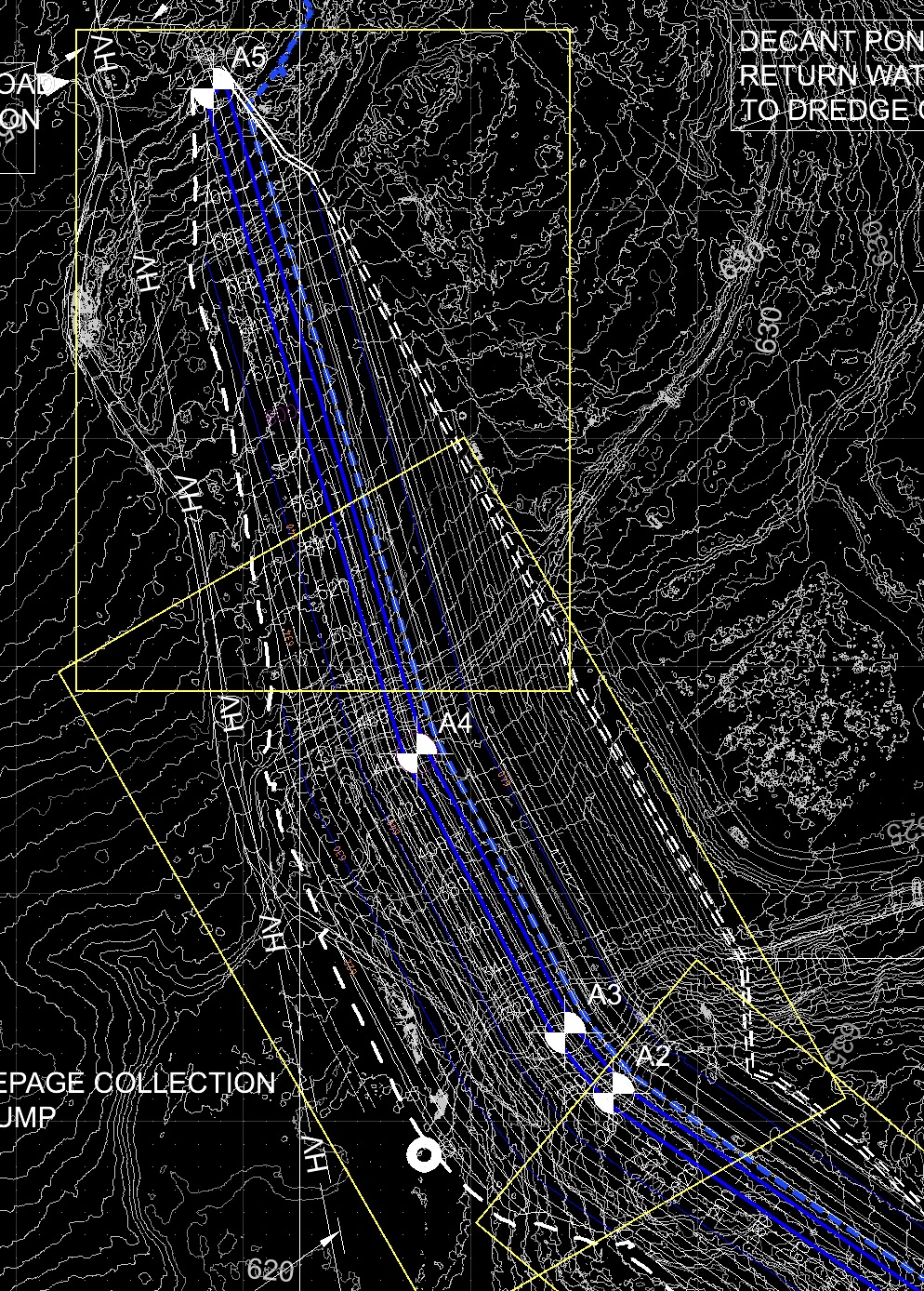
Create a new viewport on another layout block at the reduced 1:2500 scale of the entire plan area, which will now show the borders of each of the viewport layouts.
Annotate the layout with text labels adjacent the viewport borders as required to indicate the drawing number or description of each of the 1:1000 scale drawings to assist a reader with navigation.
