The file shown and attached is opened on Windows and is a DXF AC1027 file with QCAD 3.27.1.0
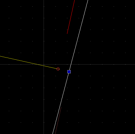
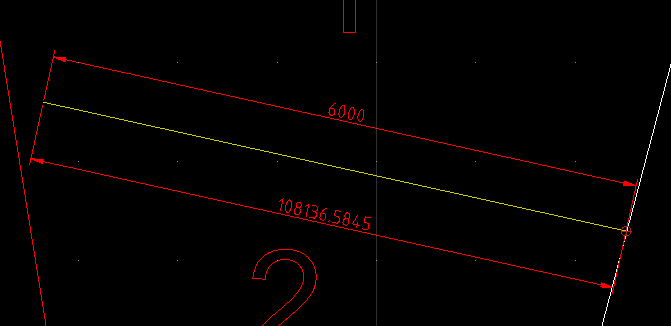
As you can see two (aligned) dimensions in the same area show wildly different length. If you move the 6000 mm dimension to the same place as the 100,000 mm dimension then it also shows the much much larger dimension. Any ideas what’s gone wrong here? It seems to make a difference if the dimension is snapping to an endpoint or perpendicular. But either way the handles for the dimension to not show it as snapped to something far away.
I’ve deleted as much irrelevant from the file as possible, but you can still play with placing dimensions and get the same effect depending on the snap settings. Make a new dimensions from the left edge of the line to the white line on the right, perpendicular. Even if you catch the theoretical intersection of the yellow and white lines as a perpendicular point, it gives the huge dimension even though the grips show that it measures the same 6 m dimension. Here’s the point I mean:
QCAD drawing tools are basically 2D, your drawing contains 3D information.
Two yellowish duplicates live at Z=53985, the white line lives at Z=-53985.
The red dimension is referring twice to Z level 53985 while the white dimension refers once to a point on the white line.
Flatten your drawing to 2D:
See menu Misc .. Modify .. Flatten Drawing to 2D.
Remark that in 2D there is a gap of 8.64505642 units between the yellowish and white line.
Because of the difference in Z this distance is reported to be just over 107970 units.
Remark that the ‘white line’ are 5 stacked duplicates.
Ah, that makes sense. Thank you. I assumed that since QCAD is only for 2d that it would flatten 3d data when opening, but of course that would not be very polite.
So QCAD keeps 3d data but just doesn’t touch it? Shouldn’t QCAD refuse to recognise a distance in the Z axis and instead project the point onto the x/y plane?
I feel like this is an unnecessary confusion for QCAD users working on received files.
(This file came from a landscape architect using ACAD 3d… no further comment required)
Drawing tools are basically 2D but QCAD handles 3D information just fine.
QCAD/CAM relies heavenly on that, the CAM part is rather 2.5D.
Still, a cutting depth in Z is important.
Automatically flatten a drawing on opening is not so opportune then.
I also must agree that the handling is not uniform throughout the application.
Exploiting 3D data or projecting things to 2D is not a simple question in all cases.
When suspecting 3D information then make a 2D copy of the file.
Loosing all Z information in the process, there is no easy way back.
For future reference could someone explain how to make a 2d copy? Since I don’t have any 3d DXF CAD software installed I can’t check if what I’m doing results in a 2d file or still includes 3d data.
Husky repeated the info given on Fri Apr 11, 2025 2:32 pm
But know that it is a one-way process.
Best preformed on a copy.
There is indeed no warning or so …
I have a custom build script that triggers on file open (RImportListenerAdapter)
And that scouts for things where Z is not zero or not really zero.
Very useful if you know that I receive drawings from very different origins.
Sometimes it is just 2D but drawn at a fixed elevation …
… I even suspect that Z+0.123e-1 or so is intentional and on purpose.
And of-course not active in my QCAD/CAM installations because 3D information is intentional .
Should be a standard tool for a 2D drawing package IMHO.