TG insert text along arc circle…
Insert text along polyline should be better, I’ll try to write a script to do that…
TG insert text along arc circle…
Insert text along polyline should be better, I’ll try to write a script to do that…
Hi,
As discussed earlier, TG is open source.
You could base your code mostly on:
By Robert S. aka riverbuoy.
The culprit sits in line 126: this.shape = getClosestSimpleShape(entity, this.pos);
A library function that essentially calls REntity.getClosestSimpleShape(pos);
For polylines this returns an RLine or an RArc that is part of the polyline and the nearest to the indicated position.
What we really want is that TextAlong.prototype.pickEntity (also) returns a reference to the chosen base entity.
The type check should then allow for RPolylines.
And why not splines? ![]()
Next issue with the existent code is that text along a polyline should be in fact text along an offset of the base polyline.
And in detail this should also be the case for lines, arcs and circles.
It would spare you the trouble of figuring out positions somewhere in thin air.
At the moment that is handled as a distance or a radius and in the latter case any other relation with the base entity is dropped.
Except its length when fitting.
TextAlong.prototype.getOperation diversifies between:
case RShape.Line
case RShape.Arc
case RShape.Circle >> full circular arc
Here you could add a call for handling polylines … And one for splines.
As is, the tool is unfit for polylines/splines, there a certain offset to segments is not the same as along an offset shape.
On the other hand … Not all offset shapes at some arbitrary distance would yield something workable. ![]()
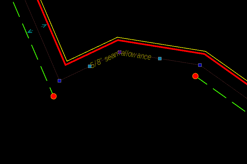
‘Fitted’ is another issue with the existent tool.
It is hard to do that on an arc without auxiliary lines or without fixing it afterwards.
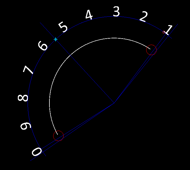
The insertion point was the cyan cross, the middle of things and placed somewhere in the void as there is no linked reference.
Here two lines were added pointing to the first and last reference point.
A bisector was added and everything was rotated so it matched again with the arc.
But the outer glyph’s are both still beyond the arc start and end orientation.
Something is not quite right. ![]()
I see it retrieving the width + spacing for each character including the last.
And that of a space to be equal to that of a minus sign again including an additional spacing.
Why it is 0, 9 … 1 instead of 1 … 0 is also a mystery, the arc is CW aka reversed and the text was placed CW.
If we use a fictive offset shape then we can use getPointAtPercent() or getPointsWithDistanceToEnd() or End or Start.
For the individual text angles there are the getAngleAt methods: At distance, percent or point.
Basically all the shape related Math can be handled by existent shape resources.
The last set of problems are the more ghostly ones:
Are all existent resources utterly correct and/or fitted or intended for the job?
Not always. In FlexPainter it was required to catch very explainable at one end to very weird errors in other situations.
Several years later:
I now know that these are mostly related to fixed internal tolerances in some resources and that a mix of those may clash. e_geek
Or, sometimes it is simply not fit for the purpose. ![]()
Also remarked that TG does not retrieves the text height from the dialog.
It seems to force the setting of the Option Toolbar … That should be an easy fix. ![]()
One can supersede an existent Addon with placing all related files in the intended path of your installation or under the user path.
Your adaption under …/QCAD/scripts/Misc/MiscDraw/TextAlong/.. would supersede the existent TG method.
Regards,
CVH
why polyline insted of spline?
just because there we can find finished lines in polylines and not in splines.
my approach is the principle that makes it possible to shorten an entity with a given distance:
split the polyline at the insertion point then shorten the 2 of the value gap between 2 of the letters and insert style TG the 2 letters etc etc
The question was: Why not polylines and splines for TG
Splines are mostly continuously but not necessarily, polylines can have hard corners unless all segments are tangentially connected.
It are the corners that make it hard to produce a nice and even spread.
That looks more like inserting characters in between fragments of the base line-art.
More in the nature of for example LineType ‘Gas Line’ or ‘Hot Water Supply’.
We can’t really compare that with ‘Text Along Entity’ because there the line-art is not affected.
Otherwise I see no need to chop up the polyline … ![]()
Also, your first statement is not complete.
Only correct if the closest segment was a bulging segment.
Sometimes called Arcs in short but it are in fact things with completely different properties.
Regards,
CVH
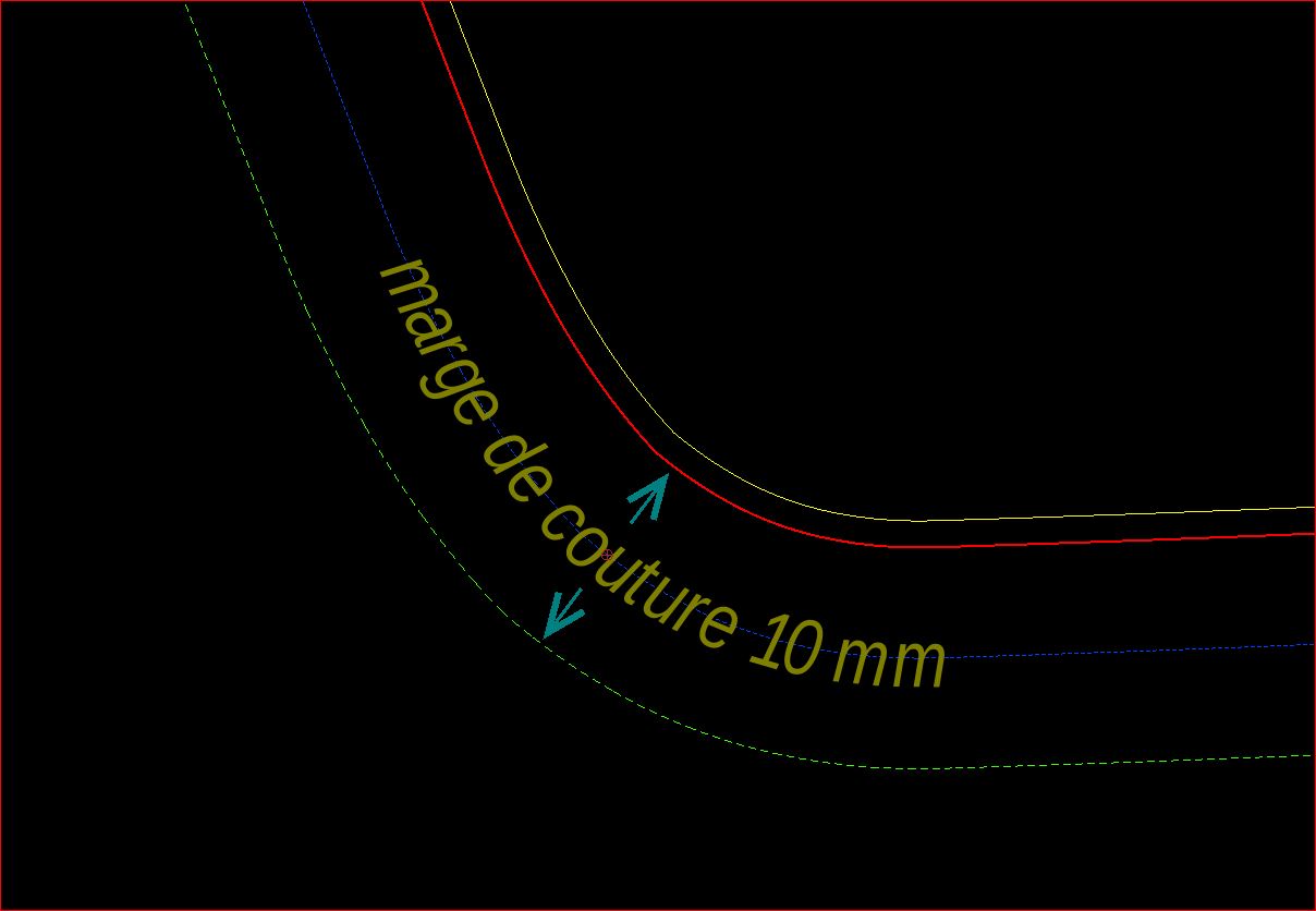
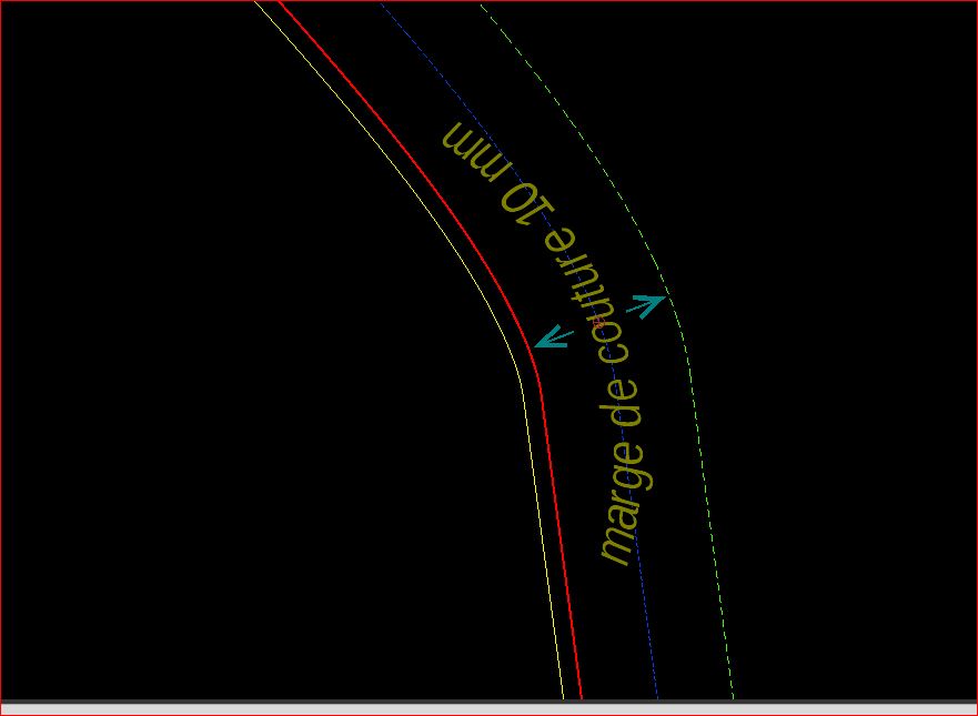
Voici ce que je souhaitetais faire avec cette fonction…
je n’utilise que des polyligne avec des segments ou des arcs mais toujours tangentiels, pas de polilygnes ‘brisées’.
le resultat avec TG
the sript works good today but there is a little bug I can’t understand…
see the pic:
Can I Use getOrientation() and what is the good syntax to apply for it?
if not, where can I find polyline orientation property as in the qcad properties panel?
I think it is a part of the solution.
Thx
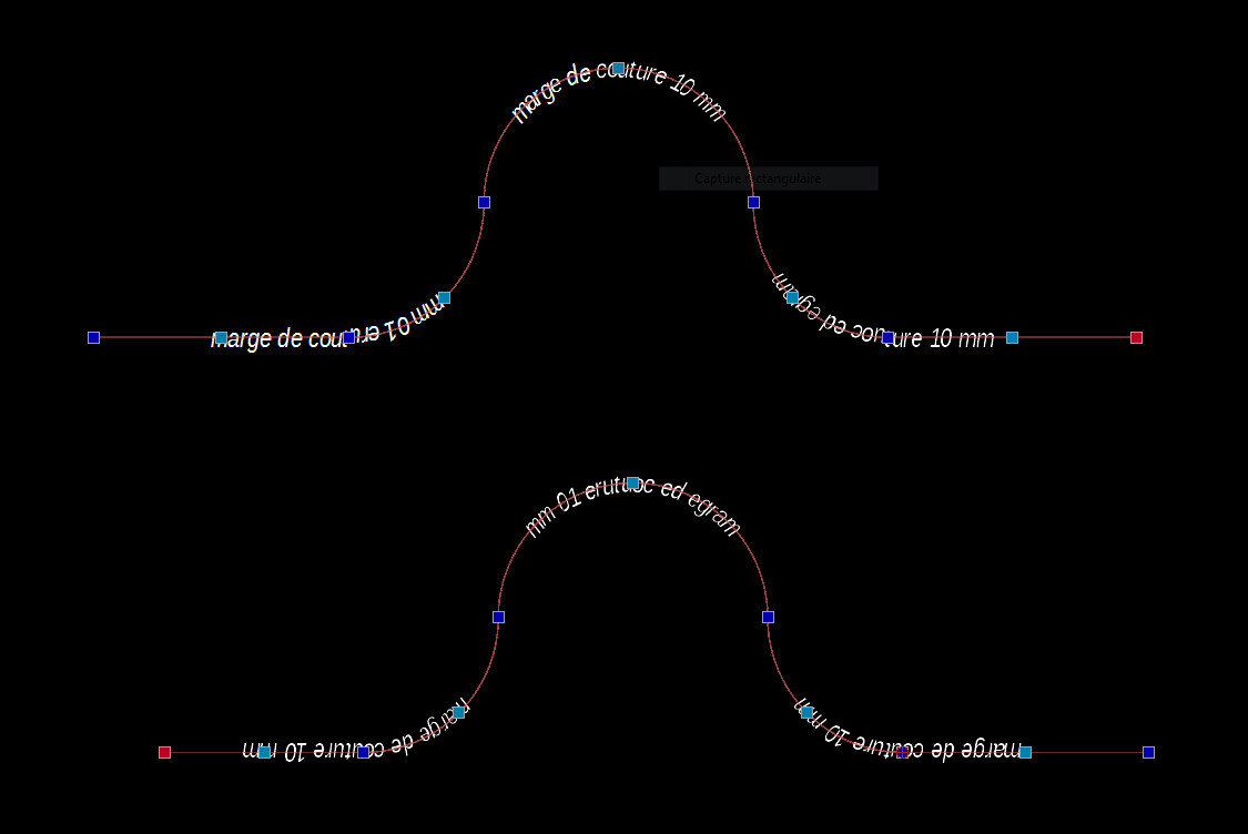
For the moment it looks more like ‘Text over Polyline’ but that is probably a minor one. ![]()
I think you need to account for Arc orientation … Reversed or not.
And that together with the overall orientation that the text must have.
Top example starts at the right, the first Arc segment is then CW, the top arc is CCW and the last arc segment is again CW.
For the bottom example that is reversed and it seems that the normal text is upside down.
Perhaps you want the text readable in all cases: readableTextAngle = RMath.makeAngleReadable(textAngle, true, corrected);
corrected is a boolean that will tell you if it was corrected an can be omitted if not required.
RPolyline.getOrientation(implicitelyClosed) will only tell you if whole the polyline is considered to be CW or CCW when closed.
But that may be ambiguous because of self-crossing or simply the nature like in your examples.
One can’t really state that the top or the lower one is definitely CW or CCW.
When implicitelyClosed = false and the polyline is not geometrically closed it returns RS.Any.
Otherwise the result depends on two segments in the lower left corner.
But you can get the local tangent angle:
RPolyline.getAngleAt(distance, RS.FromStart);
Simply add Math.PI when the text must point in the opposite direction.
For that you need the distance along the polyline from the start point:
RPolyline.getDistanceFromStart(insertionPoint);
The insertion point is assumed to be on the polyline otherwise the (first) nearest point is used.
Here I always refer to an RPolyline shape representing your original RPolylineEntity.
This doesn’t work with ‘chopped’ up segments of the polyline.
Not all methods are available for an RPolylineEntity.
Regards,
CVH
![]() It is just the polyline to insert text , the next steps for the scripts are:
It is just the polyline to insert text , the next steps for the scripts are:
make this polyline virtual…
possibility to create it with offset / existing one or spline or circle or ellipse…
modify the dialog box for the text (visible just once)
modify the letters shape / arc radius…
gather the letters of the text into a single entity (hatch…?)
this is exactly the method I used
is it what you talk about ?
That is what I meant with ‘probably a minor one’.
You are right that an offset to any base shape can be treated as a polyline.
Meaning that ‘Text Along’ can be upgraded to: Line, Arc, Circle, Ellipse, Poly and Spline entities.
This is basically how FlexPainter evolved, it started with one type and was expanded for all types of line-art.
But there is a catch with offsets … Not all will be correct, some may even be unusable for your approach.
I had a look at my FlexPainter code because I know there were issues with getting it about correct on some types.
It is Case 3 and Case 4 depending tangentially closed or not:
FlexPainter considers an open and a not tangentially closed polyline as open, as having a start and an end.
When geometrically closed and tangentially connected it is treated as closed, as endless like a circle.
Retrieving the tangent angle is basically done by:
    var castPoint = shape.getPointWithDistanceToStart(activeDist);
    var segmentShape = shape.getSegmentAt(shape.getClosestSegment(castPoint));
    var castAngle = segmentShape.getAngleAtPoint(castPoint);
For Case 3-4 it catches off distances near/over the end and forces the total shape length, for Case 3 it subtracts 2e-6.
Now I start to wonder why I opted for the angle at the closest segment … Further left undocumented ![]()
Some questions/remarks:
Best is to test if your near a node instead of near a segment end.
The included notice is:
FlexPainter having the flaws in steep curves is error-like but it is super realistic.
Twisting a roller stamp too much will smudge.
Simply avoid hard corners or small radii in your base line-art.
Not all TTF art can be morphed freely.
On the other hand, grouped as block (each one is unique) or as a selectable group of entities.
I am in the process of finalizing an addon for selecting grouped entities together base on a custom property.
Perhaps you could share the code so far and we could have a look at it together.
If you don’t want to share it in public then by private message is fine (See top right).
Regards,
CVH
I don’t know is it useful… I work with pro version and I don’t know if this script will work with free version as some functionalities could refer to pro version.
I wrote FlexPainter (Pro), 2D Centroids (Pro), DrawFromCSV (Partially Pro), all included in a standard installation of QCAD.
And many more for personal use or shared with a few users or on demand.
Pretty sure I can handle code that is intended for QCAD pro meanwhile. ![]()
Learning new things on daily base.
It may or may not work with QCAD CE, all depends, but I haven’t seen any code of the full endeavour yet.
One could prevent it from or it can be re-written to avoid Pro features when running on CE …
I think it would be a perfect (Pro) replacement for ‘Text Along Entity’ (TG) because that doesn’t support all entity types.
As is, TG is in fact ‘Text Along Line-Arc-Circle’ and as pointed out it suffers from some issues. ![]()
Surely there are other users interested if you want to share it when finished.
Meanwhile I would gladly help you further and that can be done off-forum if you want that.
Regards,
CVH
I have the version 3.25.8. pro
2 days ago, I tried to insert the last version of WidgetFactory in the script folder… result : crash
have you heard similar thing?
No, not really.
You should not merge newer source code to older installations unless you know what you are doing.
It might be downwards compatible but your older installation is certainly not upwards compatible.
Please update your QCAD version to avoid such issues.
Regards,
CVH