This is likely a rookie question but I’ve read all the threads on dashed lines and PDFs. Some of it I didn’t totally understand but I tried the various suggestion to no avail.
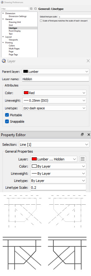
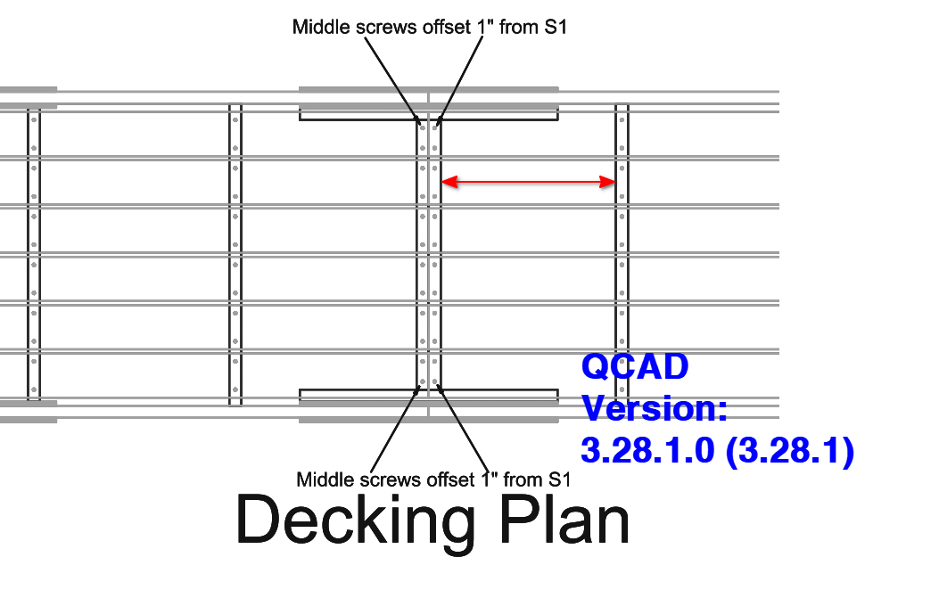
The attachment has several screenshots which I hope are helpful. At the top are various settings to provide context. The first image after those is how the drawing appears in the Paper Space (added via a Viewport which is not plotable but is also ISO dash space) and the last is what’s in the PDF. I have Screen-base Linetypes selected. The General Linetype scale is 1 but I also tried 1000 which did not have an effect that I could see. Also I am printing with Grayscale but did try Black and White.
For the PDF I use the Adobe reader. I’m running 64 bit Windows 11 up to date.
this effect is most likely based on the print paper scale. Try first to change the layer linetype. There are 3 other dashed linetipes available (Dashed, Dashed 0.5, Dashed 2) - maybe one will work.
If that doesn’t solves the issue we could help more efficiently if you attache the drawing in question to your post.
Probably, but I also remark that the selected line has LineType Scale factor 0.2
Meaning that the 30mm long ISO dash space pattern (12 on -18 off) is scaled to 6mm long, or less than 1/4 inch.
If the LineType pattern is then scaled by line weight (See: App.Prefs.) then there are 16 dashes each inch.
What strikes me the most is that the lines in the lower part of HM.png are not only continuous but also rather fat for a weight of 0.25mm
Is this drawn at 1:1 or at scale?
I have tried alternative dash linetypes. Maybe not all. No joy.
I’ve deleted the bulk of my drawing from the attached file to keep the size down but it should still contain all the layers, etc. Also included the PDF. DashExample.pdf (1.57 KB) DashExample.dxf (162 KB)
DaleEltoft,
When I go to Drawing Preferences .. General .. Linetype and set Global Linetype scale to 1 all seems fine. testLTS.pdf (4.05 KB)
Regards,
CVH
Pattern ISO dash space: 12mm on, 18mm off
Lineweight 0.25mm >> Scale Linetype pattern by line weight >> f0.25
Linetype scale f0.2
Global Linetype scale f100 (Less harder to measure up than f1000 )
Paper scale f0.04
The dash is now displayed just over 58inch long on paper (In real world inches).
12mm * 0.25 * 0.2 * 100 / 0.04 = 1500mm or about 59inch.
This seems to match very well.
At Global Linetype scale f1000 a single dash would be 15000mm or 590.55 inch long.
Or 23.622 inch on paper what is more than twice the paper width of an ANSI B.
Confusing? Sure, but it is all about factors and scales.
I’m puzzled. The Drawing Preferences .. General .. Linetype was originally 1 when I had the problem. I changed it to 1000 while trying out things as I read through past posts. I have changed it back and you are correct kind of. After making the change I clicked the Print Preview and the dashes show up just fine. However, when I then went to my Layout paper space the dashes did not appear. So it is something I’ve messed up doing the layout.
Here’s the whole file. When you open it, go to the Block List and open the paper space DRAFT32. It is when I print that to the PDF that I still do not get the dashes even though they show up in print preview.
BTW I changed the scale for all the hidden layer lines from 0.2 to 1. I don’t see what changed. (As an aside: I find all these scales on scales within scales a bit confusing.) TrussBridge_00-06.dxf (1.92 MB)
I can see that you tried to fix the issue in different places. I think we have to bring a little order into the matter …
remove first all entity duplicates which can screw up a print with dashed etc. linetypes. There are two duplicates in your drawing-find and delete them with “Detect duplicates” (MD) - all options in the Option bar ticked,
Set Drawing Preferences/General/Linetype/Global Linetype scale to 1 instead of 1000.
Next - right click on layer “Lumber/Hidden”, “Select Layer Entities”,
within the “Property Editor” - change Linetyp Scale from 0.2 to 1,
last step - Edit (YE) “Lumber/Hidden” Layer and change the Property for Linetype from “ISO dash space” to "Dashed (0.5)
Note: Using different settings in different places is always confusing - I recommend to keep it simple and avoid something like that. I learned it the hard way …
In the first file the Drawing preference was not to scale Linetypes matching with the scale of a viewport …
… One can see that in your composed screen grab.
Indeed but for some users they may be required, think of drawing in miles on an A4 paper …
… a 12mm long dash has no meaning there.
Like Husky proposed, if it is simple then keep it simple.
Dashed (.5x) pattern is 0.25" on - 0.125" off what turns out to about the double or 3 times ISO dash space at scale f0.2
Good advice regards the need for cleanup. Got that done and made the other changes. However, still no joy. The Print Preview looks fine but the Layout is not going along with the dashes. I’ve attached the modified file.
I tried an experiment. I changed the Hidden layer to Zig Zag instead of dash. The PDF file did not change although Print Preview did.
BTW it seems to me that the Drawing Preferences are unique to each Paper Space. Do I need to activate the paper space before changing them? TrussBridge_00-06.dxf (1.87 MB)
I’d strongly recommend to not enable screen-based linetypes in the print preview as this means that linetypes are shown in pixels, not drawing units. Since this depends on your zoom level and can only be applied for displaying on a screen, the print preview no longer matches your print. Screen-based linetypes are useful in model space only unless you are aware of this and know what you are doing in print preview.
@DaleEltoft,
I have reason to believe that you discovered a bug in the current QCAD version.
@Andrew
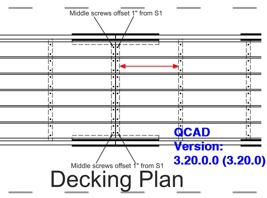
A dashed Linetype in Paper_Space isn’t correctly rendered in the current QCAD version. It is correct rendered in previous versions like 3.20.0.0.
@Husky: More likely a bug (or different implementation) in older versions.
The problem:
The drawing uses a scale in print preview (0.04).
However, the drawing also uses layout blocks and viewports.
While this is allowed, it will make things very confusing as the print preview scales the whole drawing (including borders, linetypes, etc.) and the viewports might scale individual parts of the drawing again.
Ideal solution:
The print preview scale should always be 1:1 when working with layouts and viewports.
The scaling should be done through viewports only, i.e. insert viewports that scale up / down parts of the drawing.
Alternative quick fix:
An easy fix for this particular attached drawing is to set the global linetype scale (Edit > Drawing Preferences > General > Linetype) to 25 (1/0.04). This essentially counter-scales the linetypes from 0.04 to a factor of 1.
That work around seems to have gotten me past my problem. Thanks for all the time and thought you all have put into this.
I’ll mark this solved as it gets me what I need. I’ll leave it to one of you who actually understands what’s happening to pursue if this is a bug or not.
To summarize what I understand:
The over all scaling of the layout reduced the dashed line so much that the spaces kind of disappeared. The General > Linetype scale enlarged it back to “normal”.
I believe QCAD could be improved by adding a bit more explanation to the Preferences and other dialogs of what the settings do. I suspect a whole book could be written on all the scaling effects.