I just tried QCADCAM the first time. I creatred a simple square size 30mm and tried to generate g-code. The cutter size is 2mm.
Independant of my chose to cut inside/outside/on the line I get the same G-Code as result.
I’m doing somthing wrong, but I can’t see it.
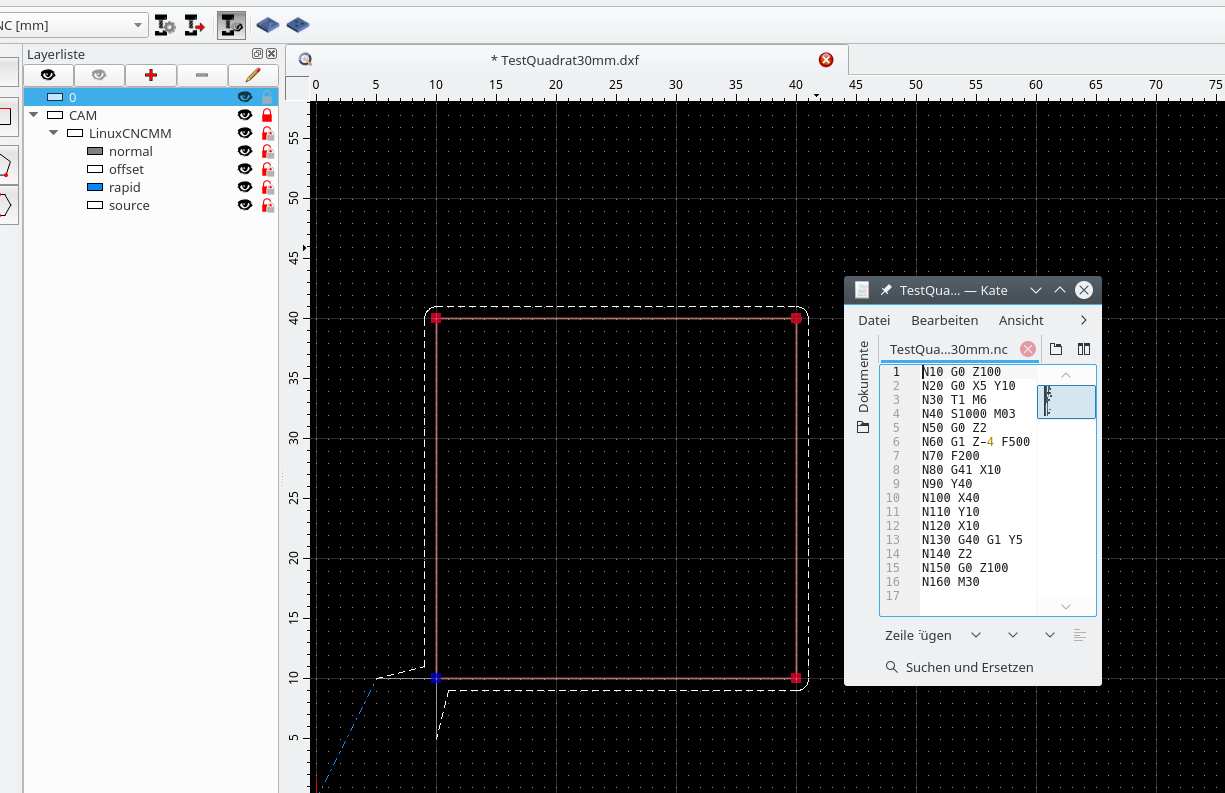
The generated path has the needed offset of 1mm, please see picture (cutting outside), but the G-Code speaks of X10/y10, should be X09/Y09 …
My version of QCADCAM is 3.19.2.0 (Linux).
You’ve chosen a postprocessor that uses G41/G42 for cutter radius compensation. This means that your controller will calculate the offset (if it supports G41/G42 at all).
If your controller does not support G41/G42, you need to choose a postprocessor that exports the offset coordinates instead (e.g. “G-Code (Offset)”).
From your screenshot, I guess that you are using the postprocessor for LinuxCNC which does support G41/G42, so your output should work fine for you.
many thanks for your quick reply. You are right supposing I’m using LinuxCNC. With your hint I could see that (I suppose) the generated g-code is missing an important command, see this info from LinuxCNC (Tool Compensation):
“Cutter compensation uses the data from the tool table to determine the offset needed. The data can be set at run time with G10 L1”.
In my case the preprocessor created code without that G10 L1 information resp. tooltable, so my tool has diameter zero and the cutter follows the original edges.
If I’m right, can I influence myself the preprocessor for LinuxCNC and correct it?
I’d like to avoid entering this info manually after every new creation of g-code, I’m sure I do forget this at least once.
Yes. The post processor is in your QCAD/CAM installation directory under postprocessors, for example LinuxCNCMM.js. It’s an ECMAScript (“JavaScript”) file. If you can attach an example file that works with your setup, I’m happy to help.
Hi Andrew,
thanks for your offer. I have two ideas to succeed. For both I need the programmers help.
The G-Code I need concerns the comand to set the tool table: G10 L1 Px Ry, where x is the Integer# of the tool (variable [T] stands for uppercase t plus the tool integer number, so not usable here) and y stands for the tool radius for which we easyly can use variable [TR] = ToolRadius.
So first we need a new variable for a solution:
this.registerVariable(“toolNumber”, “TN”, true, “P”, 0);
Now we have two posibilities:
a loop at the beginning of the gcode file to set the tool table like:
…
N50 G10 L1 P1 R1 //Tool1 with radius 1mm/diameter 2mm
N60 G10 L1 P2 R2 //Tool2 with radius 2mm/diameter 4mm
…
or we use the internal loop and send the command with every tool change:
…
N30 T1 M6
N40 S1002 M03
N50 G10 L1 P1 R1 //Tool1 with radius 1mm/diameter 2mm
.
.
N300 T2 M6
N310 S1002 M03
N320 G10 L1 P2 R2 //Tool2 with radius 2mm/diameter 4mm
…
after my opinion: I’d prefer solution 1 because you can better control the tool table at the beginning of the file.
for solution 2 we need a script like:
file start -
include(“LinuxCNC.js”);
function LinuxCNCMM(cadDocumentInterface, camDocumentInterface) {
LinuxCNC.call(this, cadDocumentInterface, camDocumentInterface);
I’ve attached a first attempt at exporting a tool list as part of the header.
This file replaces the existing file postprocessors/LinuxCNC.js. The configurations LinuxCNCMM.js and LinuxCNCIN.js are derived from this configuration and are both affected by this change. This has been tested against QCAD/CAM 3.19.2.
Please let me know if other changes are needed to make this work with your controller. LinuxCNC.js (1.16 KB)
today I tested your new cde with success.
Thanks for your help. Maybe you allow me to mention a whish: a tool to generate bridges to fix the part you cut would help me a lot.
Are there any plans to introduce it or something simular?
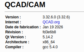
I am using version 3.26.4 of QCadCAM with Ubuntu 24.04.
I am experiencing the same issue described above.
The tool offset is not being applied.
I have copied the generated G-code below. Could you please let me know if I need to replace the linuxcnc.js file as well, or if there is another issue?
Hi,
The topic is from 98 months or about 8 years back. (QCAD/CAM 3.19.2.)
It is listed as ‘Solved’ by the original poster.
Your current <LinuxCNC.js> includes the fix, see G-Code line N10
At best you should have started a new topic.
On the older PHP forum it was also required to indicate your postprocessor and/or include at least a source document to replicate the issue.
Are you using a calculated offset or the G41/42 approach?
Because I don’t see the G41/42 instruction.
The calculated offset by QCAD should be left or right from the source shape by 1/2 tool diameter.
Then your Linux driver should not add an extra offset based on the G10 L1 Px Rx (…).
This instruction merely updates the tool list data of LinuxCNC.
It should be straightforward that the programmed data must match with the real tool.
Thank you for the information provided. As for the previous post, it explained my problem very clearly, and it is exactly the same. That is why I chose to include my query there.
As the previous post indicated, I do not wish to edit the .ngc file manually.
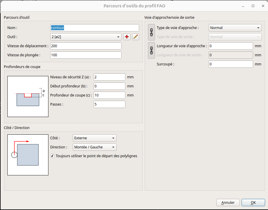
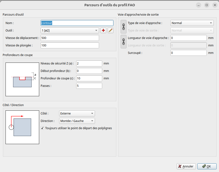
The generated G-code that I included in my previous post was created using the following QCadCAM settings (see screenshot below).
Is there a specific setting I need to configure so that the settings specified in the graphical interface are reflected in the G-code (commands G41/G42)?
Hi,
Postprocessors ‘LinuxCNC [mm]’ and ‘LinuxCNC [in]’ (LinuxCNCIN.js and LinuxCNCMM.js) use G41/G42. Then the preprocessor of LinuxCNC creates the offset depending the tool diameter and G41 or G42.
Postprocessors ‘LinuxCNC (Offset) [mm]’ and ‘LinuxCNC (Offset) [in]’ (LinuxCNCOffsetIN.js and LinuxCNCOffsetMM.js) use offset paths created by QCAD.
The term ‘Offset’ should be self-explanatory.
The export is quite different.
Offset path(s) to left or right or exactly the contour of the source shape(s) for G41/G42. That last without Lead In/Out.
The above profile is configured to generate an outer offset of 1 unit.
By QCAD or by LinuxCNC depends on the used postprocessors.
It seems to me that the file generated by LinuxCNC [mm] still does not take the offset into account, whereas the offset should be integrated automatically (G41/G42).
However, with LinuxCNC (offset) [mm], the G-code shows a different positioning of the corner points of the rectangle.
I will test both files on my CNC machine tomorrow to see which of the two takes the offset into account.
It seems to me that this should be corrected.
Thank you for your patience.
Hi,
Replicating the issue would have been easier with example drawings.
Both exports DO NOT include a G41/42 and a G40 afterwards.
This is expected for the <contour.txt> export.
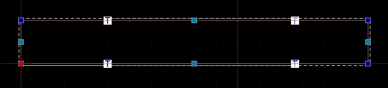
It traces a rectangle starting at (0.0, 0.0)
Then Y+20, X+160, Y-20 and X-160 (N70-N100).
And that repeated 5 times stepping down in Z, from Z-2 to Z-10.
Exactly the contour of the shape as expected.
But a G41 (left compensation) is missing.
The problem is probably the Lead In/Out.
Set to ‘Normal’ with a zero length approach path.
This parameter entry should be considered as an error.
Also mentioned in the LinuxCNC documentation:
“The only caveat is the programmer must program the lead in move to be at least as long as the largest tool radius that might be used.”
Set this to for example 5 (mm) and the export includes the G41.
Allowing zero is considered a bug, please report this on QCAD Bugtracker.
Without an approach route you could opt for ‘LinuxCNC (Offset) [mm]’.
The cutter should then plunge at (-1.0, 0.0) and trace a rectangle of 22 by 162 with rounded corners.
Not the case for your offset export, again because a zero length Lead In/Out path Is used.