Has anyone successfully created g-code output to operate a 3018 Prover engraver?
I have tried nearly every available CAM output configuration and have not gotten any reasonable machine movements.
I have created designs in QCAD 3.27.6.0 (3.27.6) on a WIndows 10 PC.
I have the latest UGS software that will control machine zeroing and jogging and has run g-code programs from other users.
Help with getting this working would be greatly appreciated.
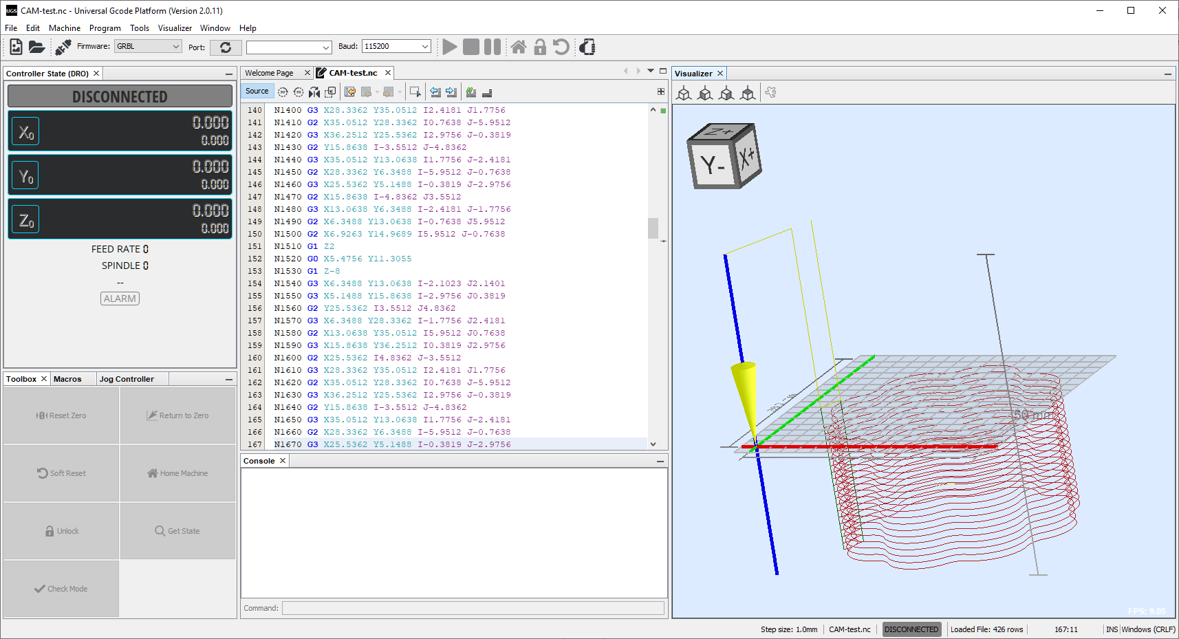
not knowing which commands are supported by your controller/machine I created one g-codeI with “G-Code (G41/G42) [in]” and one with “GBRL (offset) [in]”. Loaded both g-codes into the UGS software and at first glance both are looking pretty good to me. My impression is UGS has no problems to read g-code created by QCAD/CAM.
First, this is rather a topic for the QCAD/CAM forum.
You could REPORT your own topic and ask the moderators to move it to the appropriate forum.
It is the purpose of the CAM postprocessor to deliver a G-code dialect that is understood by your CNC controller board software.
From your description I take that this is a 3018-PROVer and the Universal Gcode Sender software.
The 3018-PROVer is sold with a variety of controllers.
The software can work together with several kinds of controller boards.
It would then boil down to Grbl and both an inch and a mm postprocessor using offsetting are provided in QCAM.
I take that the hardware side is functional and UGS is controlling the 3018 just fine.
Grbl comes in flavors and UGS is very versatile.
Perhaps you could provide us a working G-code file.
We could help you better from there.
I’m learning the 3018 Prover hobby cnc machine. I made a simple icon file in QCADCAM (in mm) and used the CAM Export and got following lines of code that seems incomplete (I’m also new to QCADCAM):
N1&G99
N2 Z0.000G92
N3 G90
N4 M2
I tried the CAM Legacy Export and got a good .NC file that worked on my 3018 Prover after deleting the first line: N10 G00 Z100 which is a default Z-Safety parameter (the 3018 Z-axis has about 35mm travel). The file has 480 lines of code which seems like a lot for a small test.
While troubleshooting my initial operation of the Prover I tried several open-source control software; Candle (came with Prover), USG, and OpenBuilds Control. They all work but I think they prefer files with metric dimensions, OpenBuilds Control supports inches.
I also imported my QCAD .DXL file into Lightburn to test the laser configuration of the 3018 Prover and it worked too.
You probably didn’t create a toolpath to export.
The export of the G-code is not incomplete, it is completely empty.
It all depends, single pass, multi pass, several toolpaths, …
G-code is textual and can be several ten to hundred thousand lines long or even much more.
Maybe you can include some sample files for us to take a look.
Thanks for the information. I realize now that I hadn’t done the toolpath operation. That must be one difference from the legacy export. Being new to the hobby cnc process I was happy to get good first tests of the router and laser using a variety of tools. I’m learning, at least I know that QCADCAM produces code my machine can use.
I’m wondering what the Z-safety parameter is for. I saw in the preferences where I can set it.
Z-safety is a height in Z where your setup can travel at maximum Feed without hitting something.
Think of clamping features or other obstructions.
Mostly used for rapid G0 movements.
As engraver I even have two safe levels, a local and a global one.
Local to retract a bit so my engraving point just hovers freely over the work-piece.
Global to move on to the next piece that is clamped on my bed.
Retracting takes time and I don’t want to retract fully several hundred times for each sub-path