I am running QCad-pro on MacBook pro, M2-pro, MacOs 13.5.2.
I have a problem with displaying arcs in DXS that are generated by 3D EM software (CST).
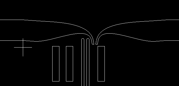
Some arcs or complex polylines are displayed with extra point added to them, making them a closed path although they are no so.
Using a different viewer for the same file does not shows this problem.
The polylines constructing seems indeed off …
… For the record:
They are geometrically closed, logically they are open.
It are polylines with line segments, there is no arc to it, all bulge factors are zero.
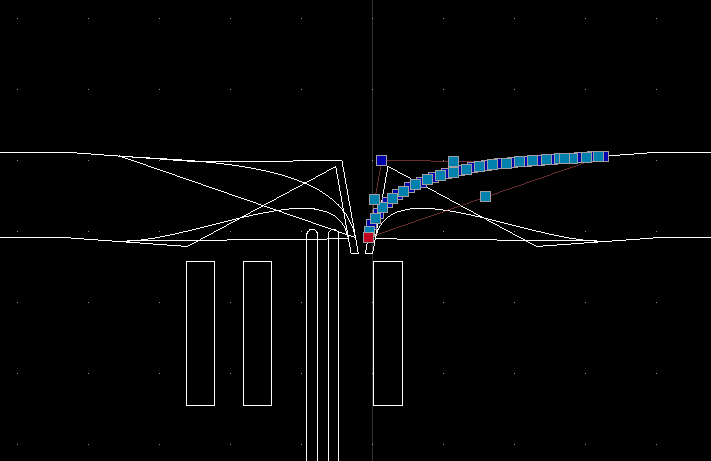
There is nothing we can do, the indicated polyline (handle = 0x77) has 25 well defined vertices and QCAD renders them all.
I presume that QCAD did not add these extra nodes by itself.
The shapes these extra nodes form look as a construction box to create the approximated curve tangent at the connection points.
Another problem is that the ‘faulty’ end nodes coincide with ‘good’ nodes.
One can not pick and drag the ‘wrong’ one by itself.
Only the first node can be safely removed with Delete Node(s) (OD) because the method looks forward starting at index zero.
Off course one could then reverse the polyline and again remove the starting nodes what were the ending nodes.
The danger exist that you don’t have an overview on what to indicate to remove.
For the indicated polyline I fooled the starting vertex and the ending vertex.
Vertex Index 0 = (-0.061099, 14.902346) … Changed X and Y to 10.0 => (10.0, 10.0)
Vertex Index 24 = (3.256635, 16.048931) … Changed to (10.0, 20.0)
After that I could remove the last three and the first node with Delete Node(s) (OD).
Similar procedure for the other 3 odd looking polylines.
Please also have a look at the hole or slot at about (-9.0, -20.0).
That looks like ellipses but don’t come even close, both are created in an odd and not symmetrical way, malformed and have dents.
It are polylines with a mix of line and arc segments.
Segments are not tangentially connected.
Your file has unit ‘None’ set. For now this is not a problem, essentially CAD is in unnamed units.
It start to play role when for example copy/paste to another file in another unit, printing and so on.