Hi, and welcome to the QCAD forum.
IMHO there are no Z coordinates different from zero.
Flattening a drawing that is already 2D has no further effect.
It won’t solve any of your issues.
The QCAD representation is perfect.
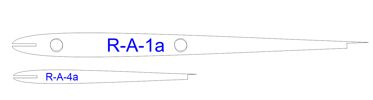
Model_Space shows 6 entities in total: 2 ribs outlines, 2 additional ‘circles’ and 2 text entities.
The top of 2 ribs is a Block Reference based on Block ‘*R20’ what already includes 2 holes.
The leftmost hole has a duplicate: A Block Reference based on Block ‘*R21’.
The rightmost hole has also a duplicate: A Block Reference based on Block ‘*R22’.
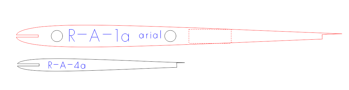
When selecting entities that are superimposed try selecting with holding down the ALT key. 
You should already fix Block names because starting with an asterisk is an invalid name (= Anonymous block).
- QCAD Pro .. Misc .. Block .. Fix Block Names
You could consider to remove the (almost) duplicates.
You could also consider to replace the circular shapes by real circles …
…  If you would be able to locate the correct center (See lower).
Eventually exploded to Polylines or exploded further into 2 Arcs by QCAD if that is required.
I would expect more holes to make the profiles even lighter.
In all 3 Blocks a circle is represented with a polyline with 2 semicircular segments.
‘Arc like segments’ or better ‘Bulging segments’ because one can convert them in both ways but never exact.
Bulging segments have end-points, Arcs have end-angles, an Arc has a center, a Polyline segment has none.
(Before anyone disagrees: QCAD explodes polylines internally for snapping to centers of Arc like segments for example)
For a perfect semicircle we expect them to have a bulge factor of 1.000…
Comes from bulge = tan(sweep/4) => tan(180/4) = 1.0
A fully circular ‘Arc like segment’ is not possible: tan(360/4) = tan(90) = Error (= infinite)
QCAD automatically prevents that on exploding a circle, on converting a circle to a polyline, … , on saving and on loading.
I suspect that these polylines are not generated by QCAD:
- Would be a logical closed Polyline with 2 vertices, not as open with 3 vertices.
- The 2 vertices would be at 0 and 180 degrees.
- Both the bulge factors would be 1.000 exactly.
Why fablab displays them incorrect I can not tell and is outside the QCAD scope.
It has to do with the bulge factors and the orientation.
The third vertices typically has a bulge factor equal to the second.
So said ‘circles’ in Block ‘*R20’ are drawn CW and in Block ‘*R21’ and ‘*R22’ they are drawn CCW.
Exploding the ‘circular’ polylines to Arcs reveals:
- Top Arcs in Block ‘*R20’ have a sweep of -174.85847228
- Bottom Arcs in Block ‘*R20’ have a sweep of -185.14143425
- Top and bottom arc of one so said circle don’t have the exact same center, the radius is almost 2.5 but not exact and not equal.
- Both Arcs making up one (almost) circle don’t connect tangentially.
Similar for Block ‘*R21’ and Block ‘*R22’ but then with positive sweeps.
 The application that generated these polylines from circles did not a great job.
The same is true for the outlines of the ribs what probably were Splines at some point.
Stepping through the vertices of the top profile reveals connecting angles varying between 179.82747097 and 181.29127169 degrees.
Meaning that the transition from one Arc to the next is not smooth, your profiles have dents and kinks.
More pronounced at the front tip where small Arcs are replaced by short but straight segments.
The bottom profile then uses a small Arc at the tip: index 1 > about 185 degrees and that is a visual kink, index 16 > about 176.1 degrees.
QCAD explodes Spline to Polylines with tangentially connected Arc like segments.
Perhaps it is an idea to do all the conversion to polylines in QCAD.
Then you could avoid to explode Circles to Polylines, see: Application Preferences .. Modify .. Explode.
Remind that the stricter the exploding tolerance for Splines, the more Arc like segments are created.
Regards,
CVH