Just installed QCAD which I’m hoping will help me get more accurate measurements into OpenSCAD.
Q1: Directly after import I had to drag around at random until I got my image visible. Is there a setting I’ve missed that will centre it automatically?
Q2: Units are set to mm, so why is it in this position apparently so far from the origin?
Q3: I’m daunted by the many tools and ‘sub-tools’! How do I now proceed to trace around my image to get a vector path, ready for export please?
Terry
QCAD Version: 3.26.2.0 (3.26.2)
Win 10 version 20H2 (OS Build 19042.985)
When you open a drawing Qcad autozoom in order to show all entities. In your case it could be possible that a small entity, not quite visible lies far from your main drawing, all it takes is a single point to generate such a situation.
Try reopening your drawing and use command “select all”, all entities should appear.
If you remain stuck, attach a copy of the offending drawing.
I’ve worked on this for an hour or so this morning but still not sure I’m going about it correctly. Hopefully my screenshots will help in getting further advice please.
EDIT:
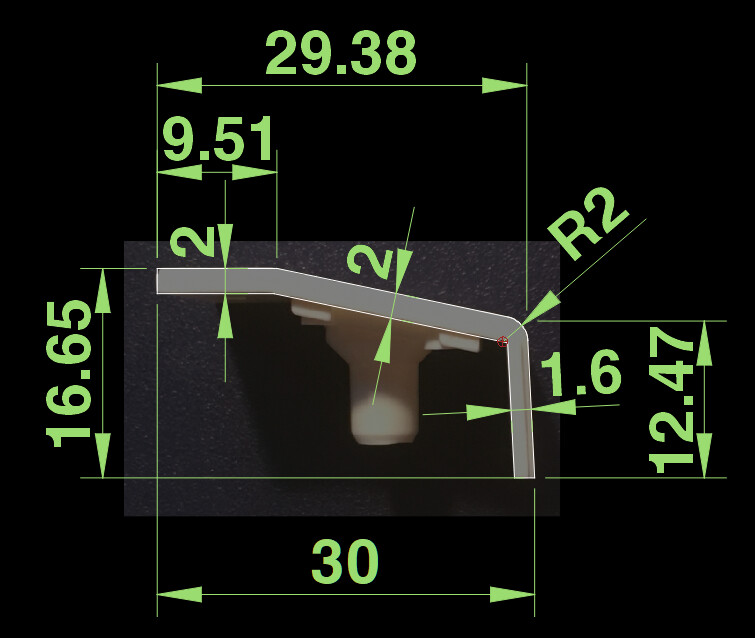
Re the dimensions and axis numbering issue, I do have two reasonably accurate physical thickness measurements: top two sections = 2.0mm and end section = 1.6mm. The lengths of each are difficult to measure precisely because their junctions are smoothed.
Perhaps this sort of task is outside QCAD’s scope? If so I’ll focus next on Inkspace, which I see has a ‘Trace Bitmap’ feature.
If you insert a bitmap with IM, then have a look High-Left
The tool will activate the Options Toolbar (Many do)
Width-Height-Angle-Keep aspect ratio(Chain)
Bitmaps don’t have an actually size stored in them, only the pixel-size.
By default QCAD takes 1 pixel = 1 by 1 unit.
To scale it proper to units you have to know an actually size in the drawing.
Scaling the bitmap with Modify .. Scale (SZ)
QCAD has no ‘Trace bitmap’ function.
So, you have to draw over it using any shape and method appropriate.
Browse the forum on ‘Image’, ‘bitmap’, … for further hints.
Hello Terrypin
Download Inkscape available free for both Windows and Linux.
Open image, select it, then from the menu choose trace bmp..
Then SaveAs dxf and open in Qcad to further manipulate..
There are lots of YouTube tutorials on Inkscape settings for tracing etc..
There are many export options too SVG is one but I usually do dxf..
Hope this helps
Cheers
John
PS Actually SVG is default file type when you save but I’ve always used dxf.. Qcad can open SVG files too.. I’m pretty sure,but I’m not on my pc atm..
Nope … it is no problem for QCAD if you know how to use the provided tools in QCAD. Trying to solve this task with multiple different software solution like Paint Pro, Incscape etc etc opens many ways for an inaccurate result.
This example is simply based on the correctness of your 30 mm measurement …
Brilliant, thanks! I’ll try those estimated dimensions ASAP.
But, as you’ll have gathered from my initial post (and my subject heading beginning ‘Novice:’), what I really want is to learn how
Your screenshot is tantalising! Can you amplify on what steps I have to take to reproduce it please? Or point me to a guide or tutorial? I don’t want to spend a month or three learning how to use QCAD’s entire feature set. Just those parts that will let me achieve the modest objective I described.
John: intend to tackle the task with Inkscape next.
Why would I want to re-open DXF in QCAD, rather than directly in OpenSCAD?
I’m not familiar with OpenSCAD but the traced image would need to be scaled as suggested .
In Qcad this is a simple process..
FYI.. 30% of my work is tracing image files, if you are using a scanner and wish to manually trace around an image then Qcad is great for this. Tip
If your scanner is A4 set the image size to A4 length top right on import as suggested by CVH
I have an A3 scanner and find this method works very accurately the other way is as Husky mentioned scale to a known size..
Cheers
John
PS I’ll download OpenSCAD today and check what features or advantages it might have
But I’m pretty sure you would only need to use Qcad for everything apart from auto tracing..
First - you have to learn how to scale (Scale SZ) a bitmap to “Real world” measurements. It is explained many times in this forum.
Then get familiar with a handful of QCAD tools like:
Vertical Line LV
Horizontal Line LH
Line from 2 Points LI
Parallel (with Distance) LP
Round RN
Trim Both TM
I used them for this example but there is always more than one way to skin a cat …
Thanks Husky, understood. I plainly do need to grasp those few basics before I can hope to confidently use Inkspace, even for my limited objective. And I hope to do that soon, despite my impatience!
But after the help here and elsewhere I have at least now managed to make some progress, thanks.
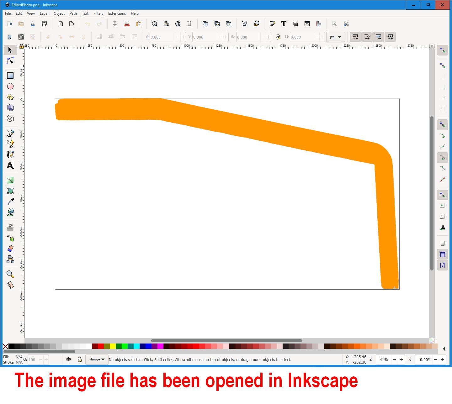
Starting from my edited profile photo opened in Inkspace…
(I don’t yet understand how to view and position things in Inkspace. Sometimes my image appeared inside the ‘box’, sometimes not. Anyway, I assume it needs to fill that box? So that’s high on the ‘to learn’ agenda.)
Just FYI, OpenSCAD is unitless. Your slicer or some other kind of STL/GCODE processor (I’m assuming you plan on 3D printing this?) would determine the unit of measure.
Thanks Ryan. Yes, I aim to linearly extrude that accurately traced or drawn profile to a height (Z) of about 21mm at this stage.
Actually each of the three surfaces has a slightly different width (Y), as well as length (X) and also tapers a bit. But I’ll tackle those complications later, together with the bolt/screw hole in the second surface and the cable hole in the third. Right now I’m focusing just on the cover. Call it stage #1 of this learning exercise!
I appreciate some scaling can be done in the slicer, Cura in my case, but I’d like to get it right by the last of these prior steps, at latest:
Overhead photo with iPhone.
Edit in PaintShop Pro, removing all but the profile due for extrusion
Import into Inkspace (which I installed on Tuesday) and trace or draw what I gather is a ‘vector path’.
Export that to SVG. (I have not yet pursued the DXF alternative.)
Import to OpenSCAD and save to STL, ready for Cura slicing to gcode.
It sounds like you’ve found a workflow that does not include QCAD. But it’s one that I have seen used before for what you’re trying to do. I believe QCAD could also be a viable tool to create a vector path from your image as Husky demonstrated. Whatever works best for you. If you need any future help with QCAD, feel free to reach out. There are some real experts here. And people like me, too.
I do have basic experience with Cura and OpenSCAD so I’m happy to help with those programs if I’m able but it looks like you have a good start on that end of things. I will say that Cura’s unit of measure is mm, so if you treat your unit in OpenSCAD as a mm, you should have a 1:1 relationship as you convert your STL to a GCODE file.