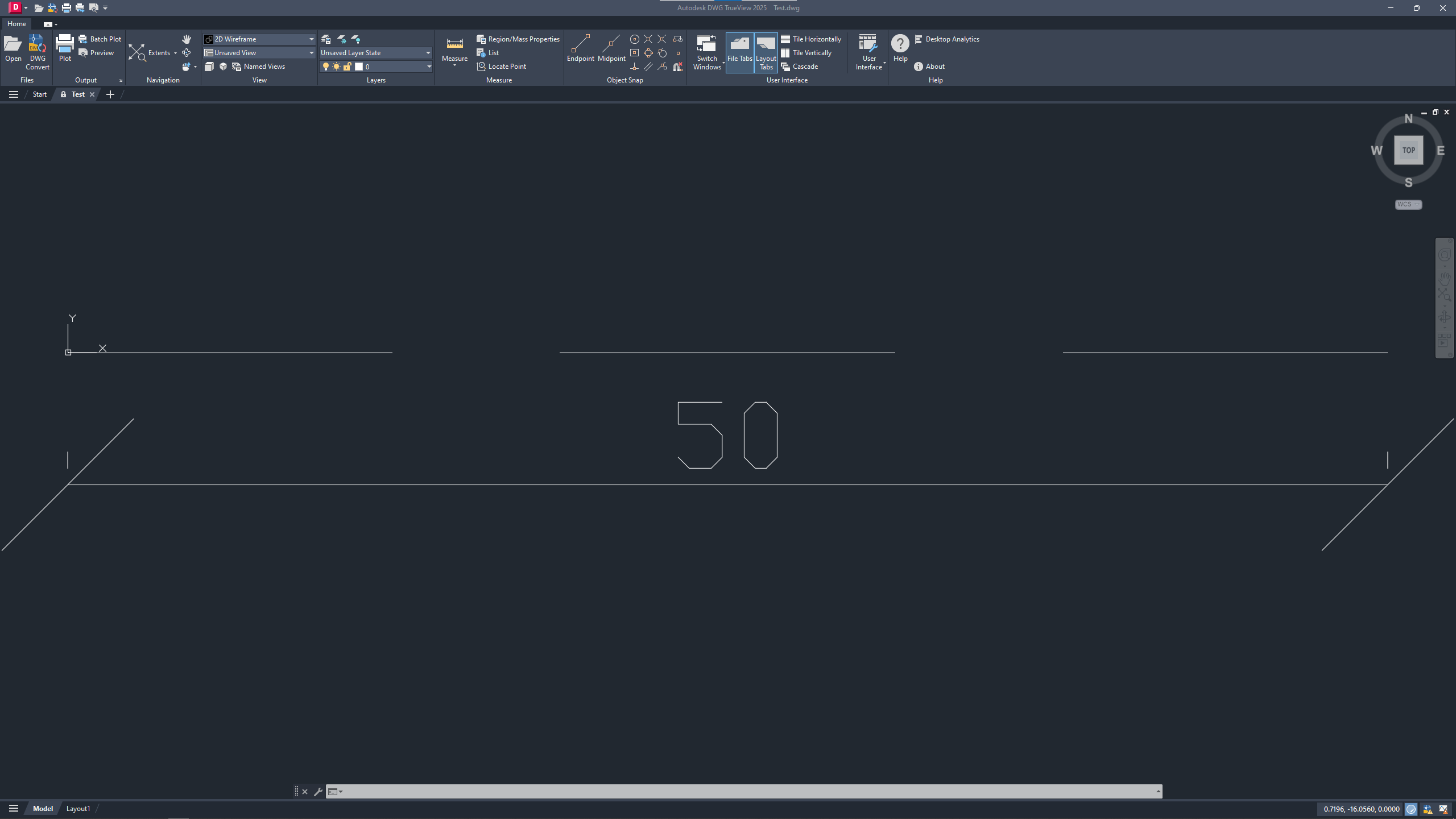
Linetypes - Different On Screen Display on Different Platforms / Software Supporting DWG/DXF

Good Evening,


Although certainly not fair to compare CAD software, as each have their advantages and compromises, and I quite like the balance stricken by QCAD Professional (currently running 3.31.2.0, Windows 10), and the tools at our disposal within QCAD, as well as the Community, as represented within this Forum.

That said, I am genuinely curious about a difference in the on screen display of certain Linetypes in DWG (or DXF) files on different platforms / software, a difference that may well persist due to the technical limitations of the DWG (or DXF) file format.
I routinely create DWGs, generally R27 [2013] DWG Drawing [OpenDesign] (*.dwg), or the analogous DXF, or the newer R32 [2018] DWG / DXF, with Layers, and Edit Layers (YE), setting the Linetype to something other than “Continuous” (quite frequently “Hidden”), or alternatively, I set the Linetype explicitly, via the Property Editor (GP), for specific geometry (usually Lines / Polylines). Occasionally, I share such DWGs directly, with someone that (unfortunately!) uses another platform / software supporting DWGs, and the Linetypes (with some exceptions, i.e. the default “Continuous”) are not displayed properly. I also share such DWGs with my mobile device (Android), view them on Apps supporting DWGs, and Linetypes are also not displayed properly.

Perhaps even the default Linetypes available on QCAD Professional, or Linetypes in general (other than the default “Continuous”), are not an intrinsic feature of the DWG (or DXF) file format? Coincidentally, and on another note, I use Hatches (most notably with Pattern “ANSI31”, and “AR-CONC”), quite successfully, which seem to display just fine across different platforms / software supporting DWG (or DXF).

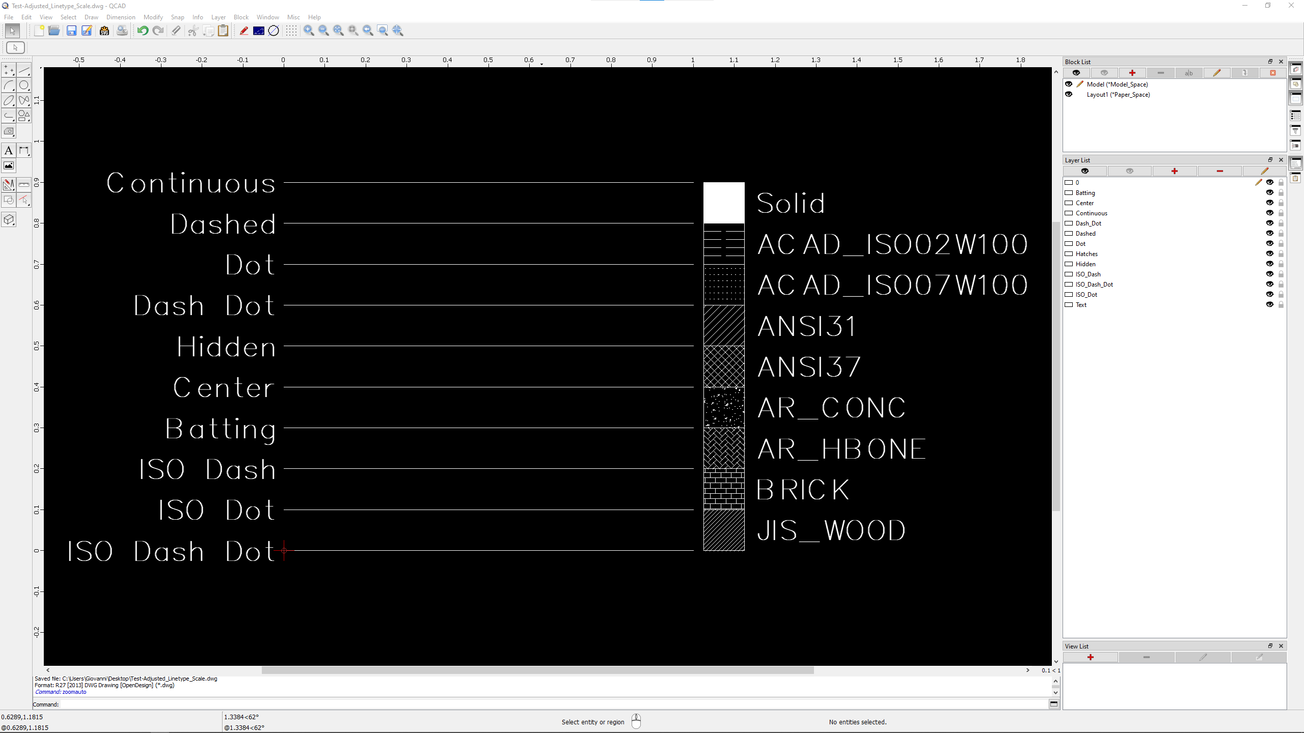
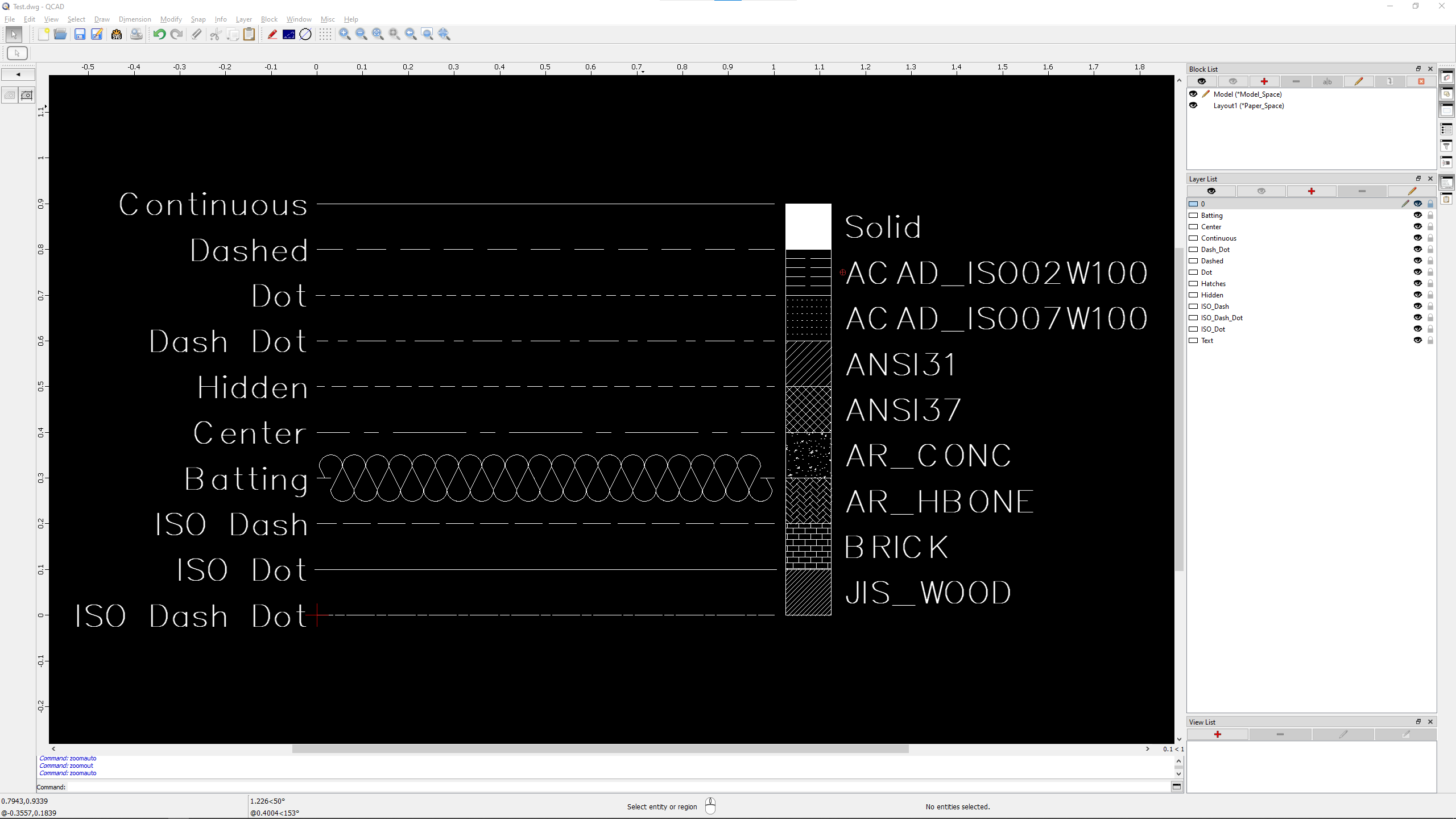
The Drawing that follows, contains, for illustration purposes, a Line from 2 Points (LI) - Line Segment (,S), of Length: 1, and with Linetype Scale: 5, the latter set explicitly via the Property Editor (GP), starting at the Origin in Model Space. This Line is Offset (with Distance) (OF) (Distance: 0.1, Number: 9), vertically, resulting in 10 parallel Lines (all with Linetype: By Layer and Linetype Scale: 5). Each such Line is then moved onto appropriately named Layers: Continuous, Dashed, Dot, Dash_Dot, Hidden, Center, Batting, ISO_Dash, ISO_Dot, and ISO_Dash_Dot (each of these Layers have their Linetype set via Edit Layer (YE) to the named Linetype). For good measure, on the right of the parallel Lines, I have also thrown in 10 Rectangles (Squares) with Size (RS), with a (random) selection of Hatch Patterns.

Test.dwg (20.8 KB)
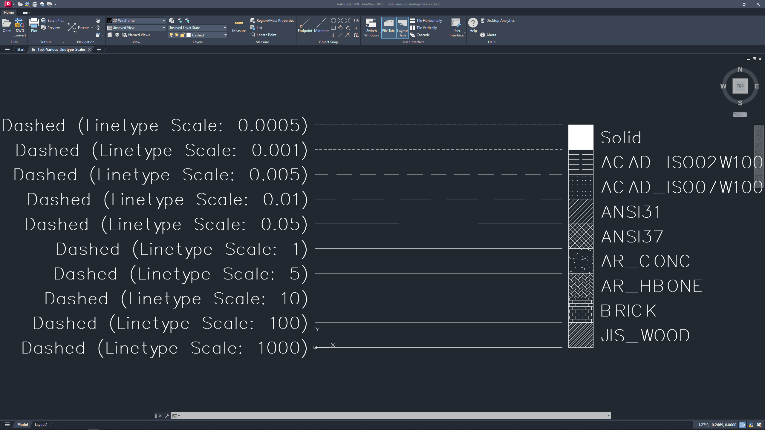
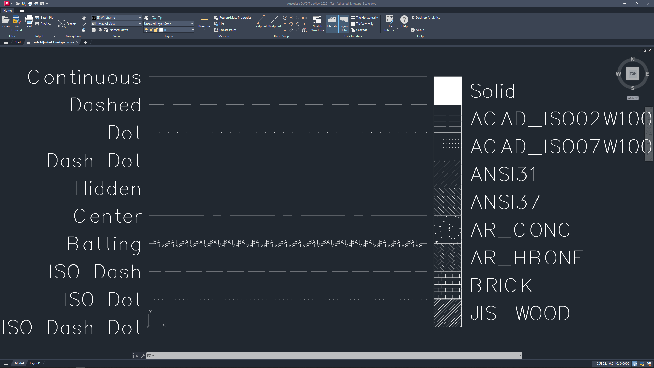
On QCAD Professional, Linetypes appear perfectly fine, on another well known, and compliant viewer (released by the creator of the proprietary file format), the same Linetypes do NOT display the same as on QCAD (they all appear as “Continuous”, with exception of Dot / ISO Dot that disappear altogether). Surprisingly, all Hatches are displayed perfectly the same on both software. Oh the joys of proprietary file format “standards”!
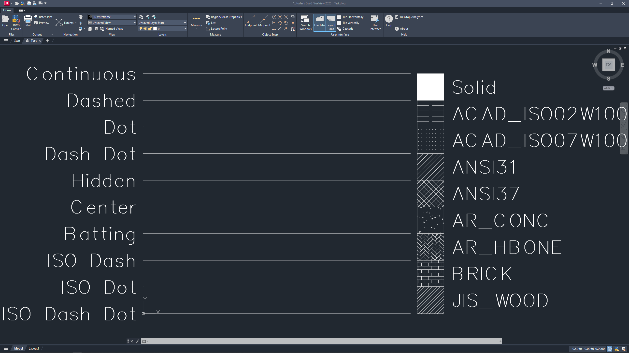

Any thoughts, or feedback (perhaps also regarding how to maintain best compatibility), are greatly appreaciated, thanks in advance!


Relevant Settings (of the attached Drawing):

  • Drawing Unit, Paper Unit, and Measurement System: Meter, Millimeter, and Metric, respectively.
  • Global Linetype Scale: 1.

Hi,
Linetypes are as per standard, there are no big secrets involved.
All basic types are defined in two .LIN files that can be found in the QCAD linetypes folder.

Hatch patterns are basically also defined by Linetypes and then rather a combination of custom types to create the desired effect.
Beside a Linetype pattern they include an orientation of the seed line and details on how that is cloned in parallel.
These can be found in the patterns folder.
Typically QCAD has a .PAT file for each pattern but it can handle several patterns in one .PAT file.


Since one can use a custom Linetype or custom Hatch patterns, a copy of the definition is stored directly in the DXF/DWG.
The information is provided as by standard, one might expect it is displayed as such. :wink:

The used definitions in the .LIN files are exactly the same. It is practically a common standard.
One can compare the QCAD .LIN files with the ones found here for example.


Perhaps there is another difference between the applications.
In Screen-based Linetypes mode QCAD uses a pixel based hybrid type so it always displays as somewhat dashed or dotted in any zoom state.
There is a preference to scale the Linetype per line Weight and a specific preference for weight 0.00mm to avoid a zero factor.
Many of your layers use the default weight and that is also set by an Application Preference.

Your drawing unit is ‘Meter’, types and weights are metric.
Dashed’ for example is defined in qcadiso.lin as 12.7 on and 6.35 off, repeated endlessly along the line-art.
All types are auto centered so that they start and end with something meaningful if possible.
The dashed line in your test file is drawn with Linetype scale 5 on a layer ‘Dashed’ with Lineweight ‘Default’.
My default weight is set to 0.25mm and types are scaled by weight.
Assuming that Screen-based Linetypes mode if OFF: 12.7 x 5 x 0.25 = 15.875
I might expect a dash that is 15.875mm long and a space that is 7.9375mm long … And that is a perfect match.
The dashes seems to be a bit longer, one need to account for twice a pen radius.
About 42 dashes per meter … No surprises or rocket science there.


I can’t replicated this deduction for the ‘other well known, and compliant viewer’.
Perhaps you can fill in the blanks.
Most probably there are some to more settings involved as with QCAD.
Perhaps type definition is handled in units, meters, while metric types should be treated in mm and imperial in inches.
That would explain the first dot for ‘dot’ or ‘ISO dot’ but not the one at 1 meter.
The space between the dots is defined as 6.35 or 3 respectively what would exceed the line length when in Meters.

It is more problematic the other way around.
Several lines intended to be Continuous as per other viewer have a random Linetype in QCAD.

And the last question is how are types represented in QCAD when drawn in a so called ‘Compliant Application’ … ?
In the above I proved that the Linetype definitions are handled correctly in QCAD.

Regards,
CVH

Thanks for your exhaustive explanation of Linetypes, and for your confirmation they are stored directly in the DXF/DWG.

Kindly allow me to add some context:

  • The Sample Drawing (Test.dwg) was created with QCAD Professional (consequently, it displays as intended in QCAD Professional).

  • The same Sample Drawing (Test.dwg), created with QCAD Professional, was then opened, and viewed, with Autodesk DWG TrueView 2025 (being from the creator of the DWG file format, and their native file format, I would assume their viewer implementation to be completely compliant with the DWG “Standard”).

As far as I am concerned, doubt remains as to why the Sample Drawing (DWG), created in QCAD (and consequently displayed correctly in QCAD), does NOT display correctly in TrueView. Perhaps certain settings (Scales, Units, etc.) within QCAD (maybe even misunderstood by myself) are affecting the Linetypes, and these settings are handled differently in QCAD versus TrueView. However, the fact that Hatch Patterns are identical on both software is puzzling.

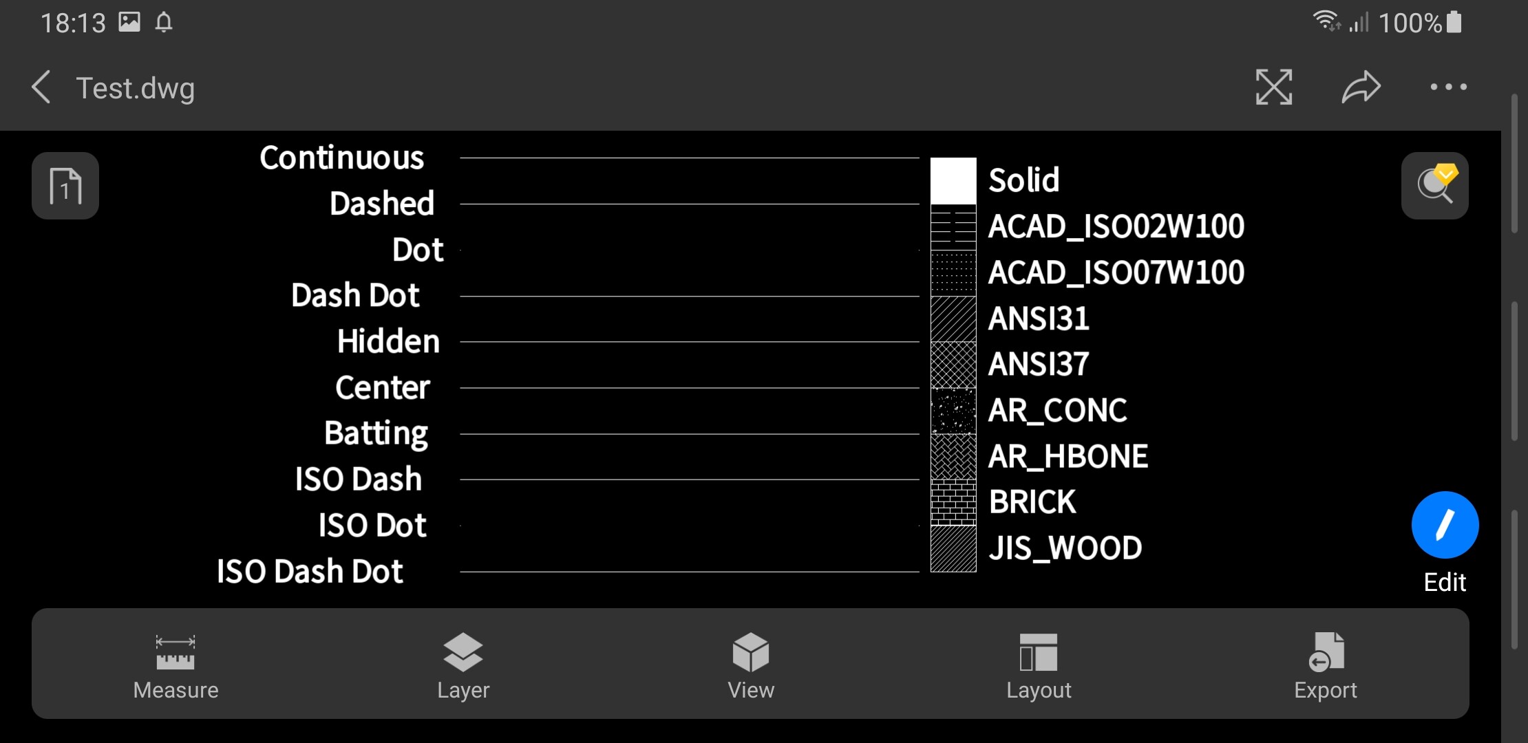
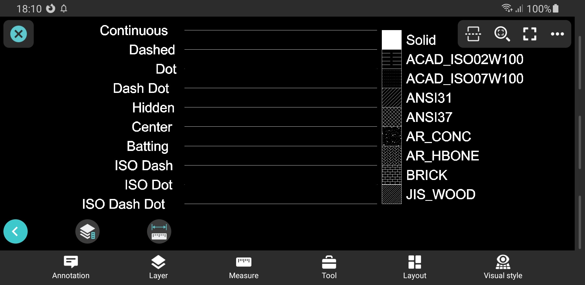
For further comparison, following are Screenshots of the Sample Drawing, created in QCAD, opened on my Mobile Device, with Apps supporting DWG (which confirm the visualization of Autodesk DWG TrueView).


I agree it would be rather interesting to see what would happen if we were to go in the opposite direction and create the DWG with other software, and then view it in QCAD. Unfortunately, I no longer have a way of pursuing this.

Best Regards!

Hi,
There are tons of example files on the QCAD forum that originate from another CAD application.
And then there are not that much complaints about the Linetype rendering.

Beside that most problems are based on 3D information, there is another red thread.

Q: What happens if you set the drawing unit to ‘None’ …?
Not only common in many attached files …
… I might recall such a common practice being advised on ACAD forums.
The reason for this eludes me completely.
Using QCAD and living in the EU, my preferences for new files are mm and metric.

CAD is basically unit-less and then the unit is merely a name that we assign to one unit.
Under QCAD it matters in a few distinct cases:

  • To scale something to paper size.
  • When we import a Block drawn in a different drawing unit.
  • Or for unit conversion in general.
  • For Linetype rendering.

Coming back on ‘None’ and Paper Scale, we also see a lot of 3th party drawings drawn at scale.
One should draw everything at scale 1:1 in the chosen drawing unit.
It spares the trouble of converting real world sizes to drawing sizes and back for each detail you add or measure up.
How that is presented on paper is governed by a paper scale, usually in a final process.
But nothing forbids you to do it the hard way, you may draw the things so that all will fit 210 by 297mm to present it on A4 paper.
Drawing at scale is old school from back in the days we drew with ink directly on paper.

Another thing you could try is setting some drawing global Linetype scale and counteract it in the entity custom Linetype scale.
It won’t change the rendering in QCAD because the true scale remains the original factor.

Regards,
CVH

Hi CVH, this happens to be the opposite case, a Drawing (DWG) newly created, and saved, within QCAD (so originating from QCAD), and only visualized in other CAD Software (the freely available DWG TrueView).

For context my Drawing Preferences regarding Drawing Unit (General: Drawing Unit) are also Drawing Unit: Meter, Paper Unit: Millimeter, and Measurement System (for line types and hatch patterns): Metric, and regarding Linetype (General: Linetype) they are Global Linetype Scale: 1, and “Scale of Linetypes Matches the Scale of Each Viewport” is Unchecked.

With your thoughtful suggestions we may have shed some light on the issue. It appears that QCAD and other CAD Software interpret the Linetype Scale differently, by a factor of 1000. Whereas, in the Sample Drawing (Test.dwg), the Linetypes displayed beautifully on QCAD with a Linetype Scale: 5, for them to appear beautifully in other CAD Software they must have a Linetype Scale: 0.005 (= 5/1000, equivalent to setting the Global Linetype Scale: 0.001). In conclusion, the Sample Drawing, and the Linetypes thereon, can display correctly on one software, or the other, but not (simultaneoustly) on both, by tweaking the Global Linetype Scale (without having to change the Linetype Scale entity by entity), or by tweaking the Linetype Scale of each entity.

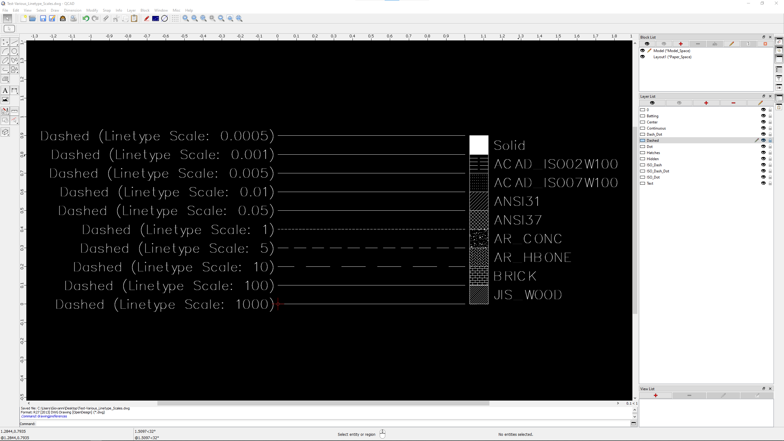
For illustration purposes, I have modified the Sample Drawing (Test-Various_Linetype_Scales.dwg), always in QCAD, focusing on a particular Linetype (Dashed), and assigning to each Parallel Line (Dashed) a different Linetype Scale (0.0005, 0.001, 0.005, 0.01, 0.05, 1, 5, 10, 100, 1000). Upon opening this Sample Drawing in other CAD Software, it is evident that the Linetype Scale displaying the most similarly to the one in QCAD (Linetype Scale: 5) is Linetype Scale: 0.005.

Test-Various_Linetype_Scales.dwg (21.5 KB)


Moreover, it is evident that the Linetypes with Linetype Scales 1, 5, and 10, in QCAD, correspond to Linetype Scales 0.001, 0.005, 0.01, respectively in other CAD Software (in each case a factor of 1000 difference in the interpretation of Linetype Scale). Fortunately, the Linetype Scale does not seem to influence the Hatch Patterns, which remain in perfect agreement between QCAD and the other CAD Software, regardless of Linetype Scale.

With this knowledge, I have modified the original Sample Drawing (Test-Adjusted_Linetype_Scale.dwg), always in QCAD, by tweaking the Global Linetype (Global Linetype Scale: 0.001).

Test-Adjusted_Linetype_Scale.dwg (20.9 KB)


Now, it does not display properly in QCAD anymore, but it is perfectly displayed in other CAD Software (certainly this is not a fix, but rather a workaround, I will have to remember to set the Global Linetype Scale: 0.001 when sharing Drawings with users of other CAD Software, and vice versa).

Perhaps this is a bug, a factor of 1000 lost somewhere? Of course I cannot rule out mistakes by the user!

Are big words. :wink:
Using the Selection Filter one can filter globally on Linetype Scale = 5.
With a selection one can change the Linetype Scale of all selected in one single action by changing the property in the Property Editor.


From your tests: Linetype Scale 5 in QCAD looks the same as Linetype Scale 0.005 for others.
Obviously, the factor 1000 (1/1000 or 0.001) originates from 1 meter vs 1 mm.

For what I knew about Linetype definitions is that they are expressed in mm or in inches.
But this conviction is gradually crumbling.

In About Simple Custom Linetypes I discover literally that they are expressed in drawing units.
The example explains that DASHDOT A,.5,-.25,0,-.25 has a dash that is 0.5 drawing units long.
Is this perhaps a misprint?

Digging deeper …
in AcDbLinetypeTableRecord Methods I read that dash or pattern lengths are ‘in AutoCAD drawing units
And that agrees with what I can read in LTSCALE and PSLTSCALE system variables in AutoCAD
The dash specifications in linetype definitions are given in terms of drawing units.

I have some expertise in Hatch pattern coding and there the custom line patterns are definitely in drawing units.
Same goes for the parameters that define the offset and the shift for each next parallel.
That explains why Hatch patterns are unaffected.

And then it all starts to make sense.
As almost everything, line patterns are intended to be in drawing units.
:arrow_right: Except under QCAD :exclamation: :question: :open_mouth:

Let’s drag in complex Linetypes.
CFX data is coded in base 9, meaning that the height of a capital ‘A’ is typically 9 units high, correlating with 1 drawing unit high.
The capital ‘A’ in Standard.cxf is therefor defined as 9 drawing units high.
The Linetype pattern ‘GAS_LINE’ exploits the Standard.cxf at scale 2.54 in metric and at scale 0.1 for imperial.
Meaning that the ‘A’ in the inline text ‘GAS’ must be 2.54 units high and that is only true for a drawing in millimeters.
Similar as the Linetype pattern itself, it is treated as in mm and scaled down by a factor of 1000 for a drawing in meters.
While a text ‘GAS’ in the standard font remains unchanged expressed in drawing units.

Treating text as in mm kinda breaks with the base 9 = 1 drawing unit rule.
Expecting something similar using imperial.

:arrow_right: There must be a reason why Andrew sticks to Linetype definitions in millimeters or inches.
See first comment in a bug report FS#624 (2012) degraded to feature request.
Another topic from 2013 and these conversation1 - conversation2 between moderators.
Yet another topic from 2016.
It is a recurring statement throughout the forum.

For the moment I am not able to find a DXF standard that agrees with that.

If we scout the ACAD forums, there are the same discussions and confusions going on. :laughing:
Some solutions are even based on a complete different Linetype set for the meter as drawing unit.
And then it seems that ACAD users must Load/Unload types with a Linetype Manager …
… Or use a template where that is already established.

Regards,
CVH

@CVH Thanks for your thoughts, and thorough research, which I have read with great interest!

Considering the Linetype Definition Format:

*linetype_name,description
A,descriptor1,descriptor2, …

And, as an example, the Dashed linetype defined as follows:

*DASHED,Dashed __ __ __ __ __ __ __ __ __ __ __ __ __ _
A, 12.7, -6.35

When drawn it should have a dashed segment 12.7 units long with a gap of 6.35 units.

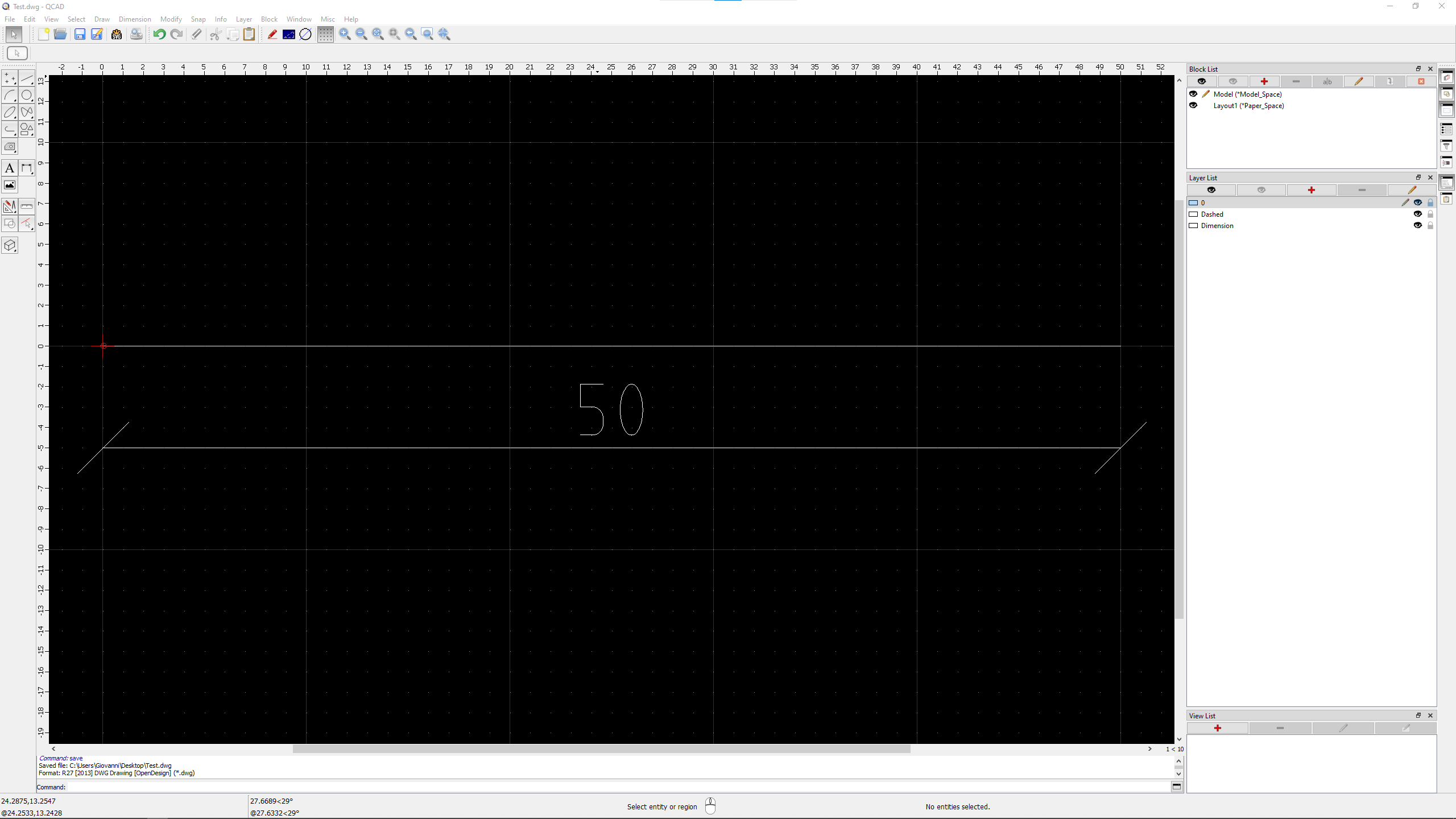
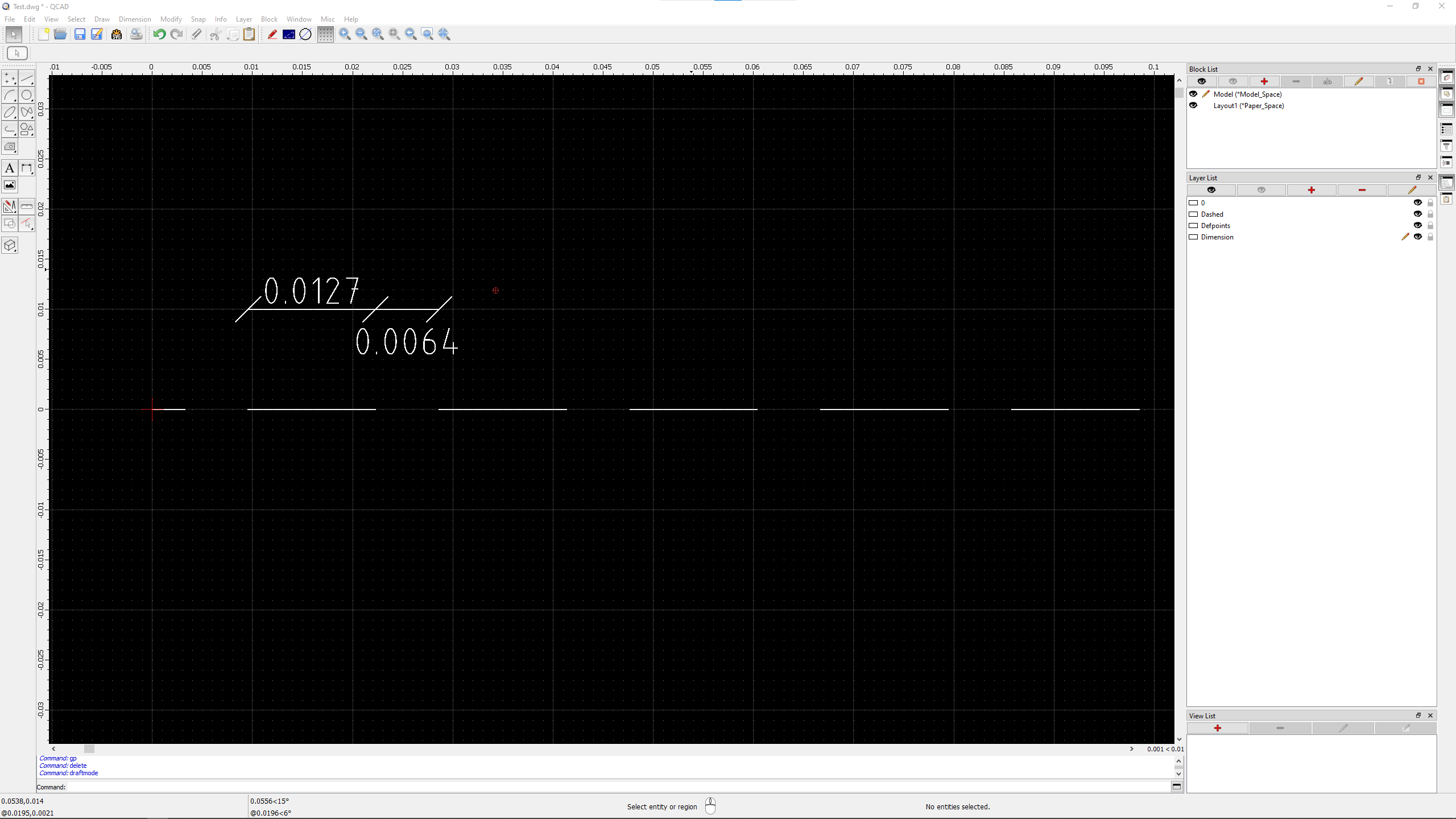
*When drawn in QCAD Professional, in the attached Sample Drawing (Test-50.dwg), with Drawing Unit, Paper Unit, and Measurement System: Meter, Millimeter, and Metric, respectively, Global Linetype Scale: 1, and Default Lineweight: 0.13mm (ISO), the dashed segment is only approx. 0.0127 units (m, or 12.7 mm) and 0.0064 units (m, or 6.4mm), respectively.
*

Test-50.dwg (18.3 KB)


Opening in other CAD Software and measuring the dashed segment and the gap, they are approx. 12.7 units and 6.4 units, respectively, as they should be in accordance with the Linetype Definition above.


Therefore, I can confirm (empirically) that QCAD and other CAD Software interpret the Linetype Definition differently, QCAD in millimeters (perhaps, unfortunately!), and the other CAD Software in drawing units. Of course, a reconciliation between the two would be fantastic!

I have yet to try your suggestion of setting the Drawing Unit to “None”, just to see if that resolves anything.

Thanks again, and Best Regards!

Hi,
For the test with Test-50.dwg a few things are omitted under QCAD:

  • With no custom Linetype scale or an additional custom factor of 1.
  • By Application Preference NOT scaled by weight.
    Typically required for ISO Linetypes (Also see qcadiso.lin line 60-65)
    Otherwise an additional factor of 0.13 is applied.
  • With an increased threshold to render entities with a large dash count by Application Preference.
    Otherwise the line is rendered as continuous.
    50 / (0.0127 + 0.00635) ≈ 2625 dashes what requires a threshold allowing that, next up is 5000 although it is an editable combo box.

Considering Linetypes in drawing units then the dash count would not have such excesses.
Agreed, there will always be situations where a certain threshold is required.


A threshold is probably more related to a rendering approach, to avoid lagging.
Patterning a line with short segments and then clipping the collection of short segments to a view.
Versus: Clipping a continuous line to a view and then apply a pattern.
IMHO: Calculating with what a clipped pattern starts and ends is less costly than defining all not visible dashes and dots.
Unless everything is visible and then at some zoom state it looks continuous again.
For example when the largest space minus pen size is less than a pixel.

If have the same reservation for the Hatching engine approach.
Cloning each definition entry patterned in parallel for a larger area and then clipping the vast collection of details to a boundary(ies).
Versus: Clipping to a boundary and then apply the patterns.
Hatch rendering may simply timeout because most of the generated details are outside the boundaries.
All depending the definitions and the scale, at some zoom state patterns would look continuous or even as solid filled.
With my Hatch pattern expertise I can even reduce the calculation cost by yet another factor.
Not looking at it as inline patterns but as traversing the cloned parallels for each entry.

I addressed Andrew on Linetypes and drawing units here and … No comment.

Regards,
CVH