Hi All,
new to forum and starting work with QCAD.
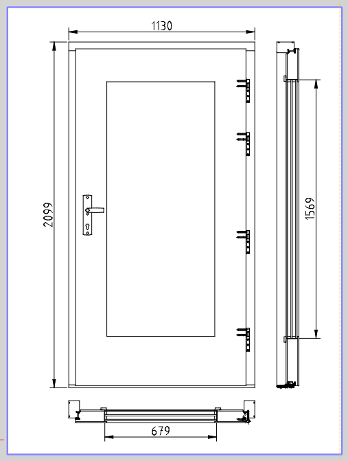
We build doors and windows, and am trying figure out if there is a way to input our frames. When we resize the window/door the frame always remains the same thickness. It’s only the glass size that changes. The unit could get wider and taller, but only the glass size changes.
Is there an easy way to do this?
For example width - frame = glass, and “frame” is a constant.
Once you’ve selected your reference point, you can hit “space” to go to the command line and specify the target as:
@-5,0
To move the frame 5 units to the left.
In another life, I wrote optimization code for a small company that made software that generated windows and material lists for small businesses, so windows are a bit of an interest.
Panchdara, In a word, yes exactly! Thanks for concisely explaining my problem.
And Markz, thanks I’ll play with that suggestion. It needs to be pretty simple to do as I will have to explain this to non technical people… e_surprised
Ignore what I said about the reference point. You can put it anywhere that it makes sense for you. If entering relative coordinates is too technical, you might be able to do it by snapping the SS target to some other object. This is where seeing the actual dwg would help.
It will be interesting to see what the pros say. I was able to stretch the door and topview 100 mm on the right side – except that in the topview (below the main door view) there are 6 lines that absolutely refuse to stretch (zestraw layer). There doesn’t seem to be anything special about them. Their layer isn’t locked. They’re just standard lines. It would be easy to fix them with the trim tool, but why should you have to ?? I loaded the drawing into another program with a similar tool, and was able to perform the stretch including the 6 lines, so it doesn’t seem that there are any hidden bits or special properties. So … interesting.
After any stretching, it looks like there are some “tick” marks along the bottom door frame that will have to be regenerated if they are required.
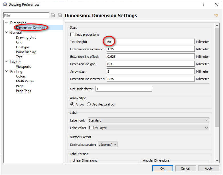
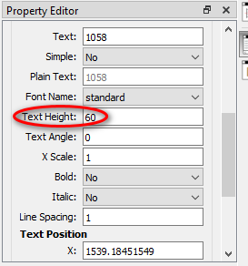
There was only one piece of text in the dwg that I could see. It appears that you can change it’s size in the property editor.
The first drawing you presented had a working paper space with dimensions. This drawing doesn’t (or at least I don’t see anything in them ) . Are you expecting modifications inside paperspace, or will that not matter?
Here’s the way that I did it. I don’t claim that it is the way to do it, or even the best way. It will be interesting to see what others say.
The way I’m doing it here avoids using the command line, though I personally find the command line easier.
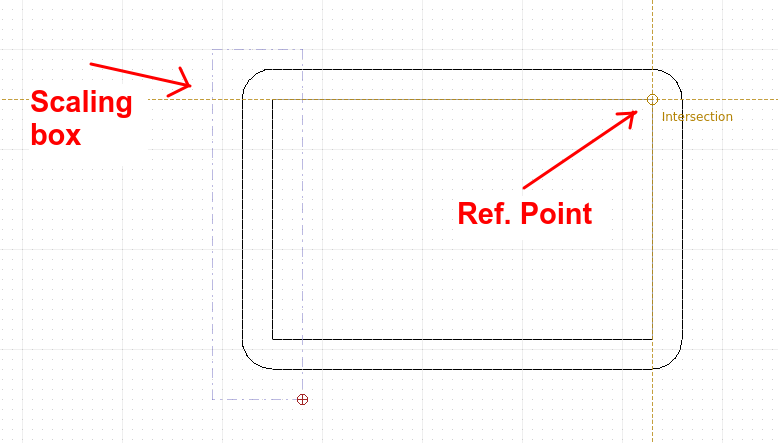
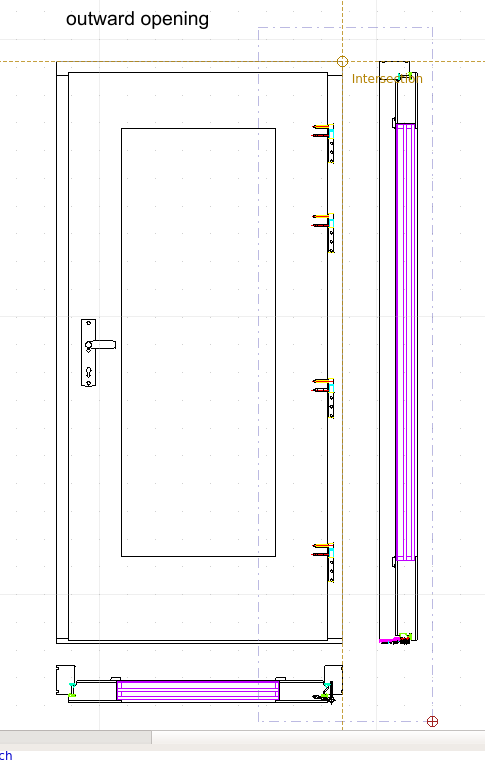
First, make sure you are using auto-snap (SA). Zoom out so you can see your entire door. Use the stretch tool (SS) and “lasso” everything that needs to included in the stretch, including the sideview of the door. Then set the reference point. Here I’m using the top right corner of the door. This image shows the SS selection and the intersection:
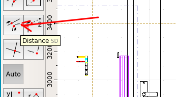
Now you need to set the target point. This will be 100 mm to the right of the reference point. Go over to the toolbar and select the distance snap (or use SD):
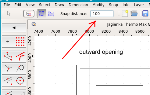
Now look at the top right hand side of QCAD. There is an option box to set the distance. Put minus 100 in the box (It is minus because we are going OFF the line) :
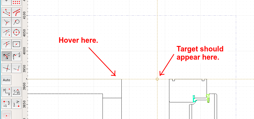
Now hover just a little to the left of the intersection point you set earlier. A target point should appear 100 mm off to the right. Left click to complete.
Escape out of the Stretch tool. Verify that the stretch has occurred correctly. Reset your snap to AUTO (SA).
Repeat the process on the 2nd (inward) doorway.
Note 1 – if you positioned the inward/outward doorways above each other, you could do it all with one stretch.
Note 2 – If your lines along the topview don’t stretch correctly, you may need to flatten the drawing to 2D and try again. That’s what happened in the first drawing you presented.
Note 3 – If negative numbers are too confusing for your non-technical people, you could set the intersection at the upper LEFT hand side of the door, and then use a positive (100) distance in the distance box.
In addition to Markz suggestion I would only try to make it bullet proof for the mentioned “non technical people”. For that reason I draw a yellow line in Model_Space, a few dim’s to have a reference to what is going on regarding the targeted measurements and a layout block for the print job. The yellow line and text hints can stay in Model_Space - printing is disabled for this layer.
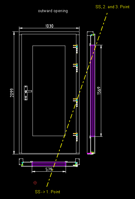
How to change the door width?
launch SS
pick end points 1, 2, 3, (2 and 3 are the same Point!)