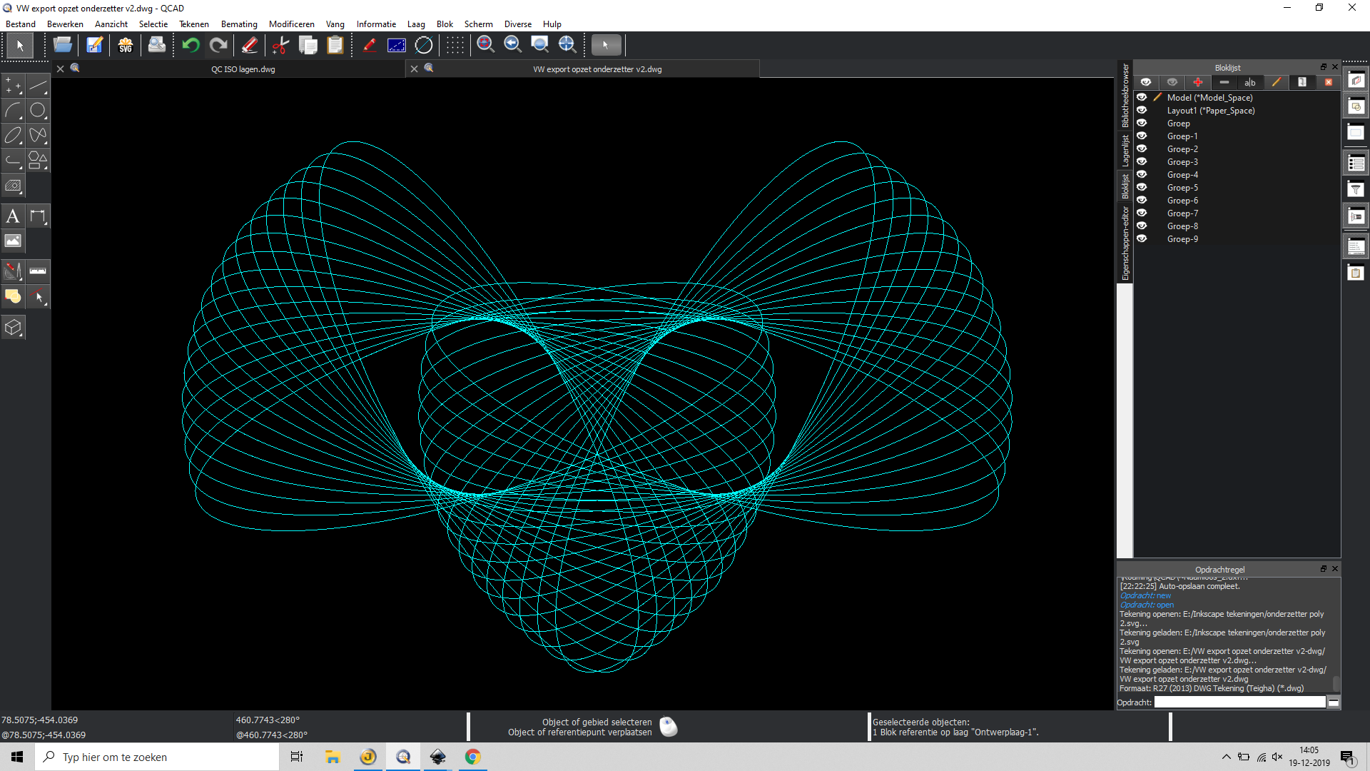
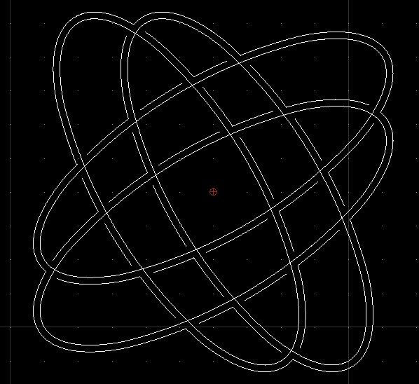
I’m an experienced cad-user and I like Qcad, but here I’m a new user and I have difficulies in a recent design for a coaster. The design is made with a lot of ovals (see image). Now I want tot make it ready for a lasercutter. The lines you see now will be halfcut and there is an outline to be made for the overall form and two small inner lines too (for the ‘eyes’). But how to make this outline/inline? In my old cad-program I could unite all the entities to a new path/spline/polyline-like object.For the inner open zone (eyes) I could have used a bucket tool to define such a ployline/spline. How can I perform such actions in Qcad?
QCAD does not have tools for boolean operations on closed shapes nor a bucket fill type tool. Both are very complex operations when arcs, ellipses, splines are involved.
For an approximation of the union (outer most contour), you can use a simple script as follows:
Open the script shell (Misc > Development > Script Shell)
Select all ellipses
Paste the script below in to the command line of the script shell. Note that this is extremely crude code without any checks that might crash your QCAD. Be sure to save your work first. You also might want to do this with a copy of the ellipses as the ellipses will be converted into polylines in the process.
This could have been a simple and elegant solution, but it didn’t work because qcad crashed. I tought: let’s do the boolean trick in Inkscape and work on in Qcad but that wasn’t easy as well.
Exported the drawing to Inkscape as svg and made the outline (that was the easy part).
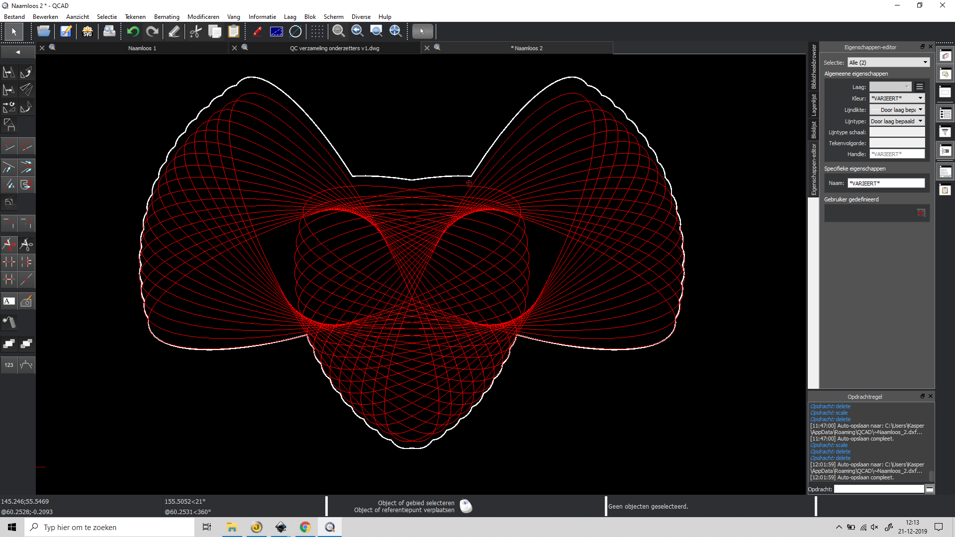
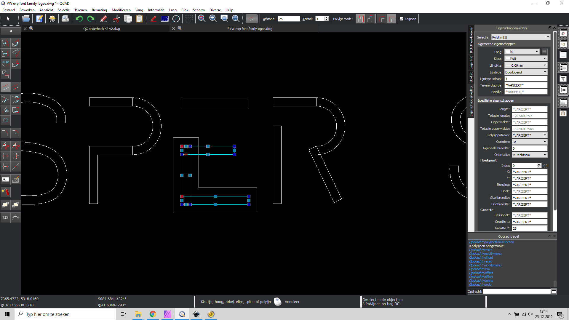
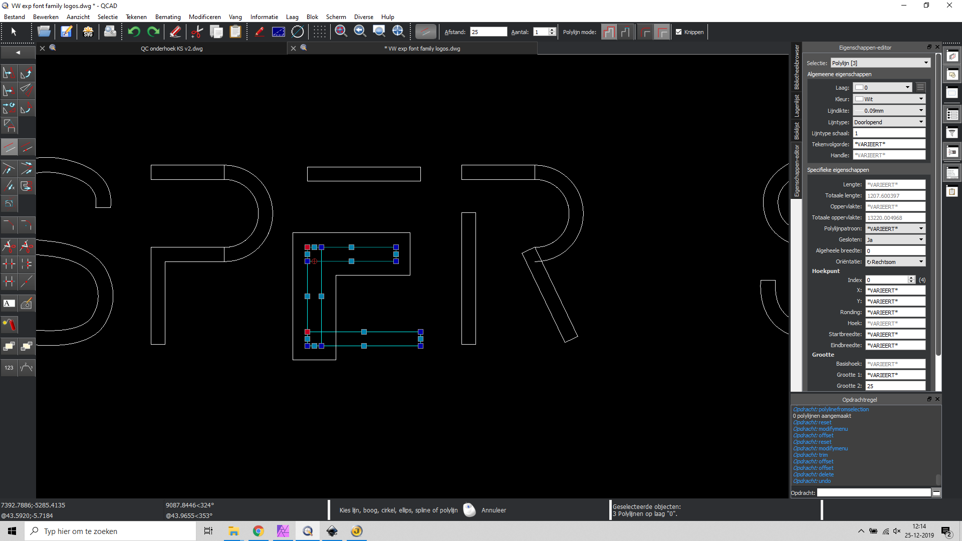
Imported the new made outline in qcad but it would not show. Strange because other shapes I made as svg had no problems. Then I exported from Inkscape as dxf12 with a better result. Transformed the splines and lines to a new polyline to find out there was a little vertical scale problem (see picture, the white outline doesn’t really fit). It is still a funny drawing but not exactly following the plan I had.
Nobody is to blaim because of my strange workflow of exporting and importing but I don’t exactly understand what goes wrong.
Is there a reason boolean actions are not supported in qcad, or is this the reason? Is there a change qcad will have them in the future or is this a irrelevant question?
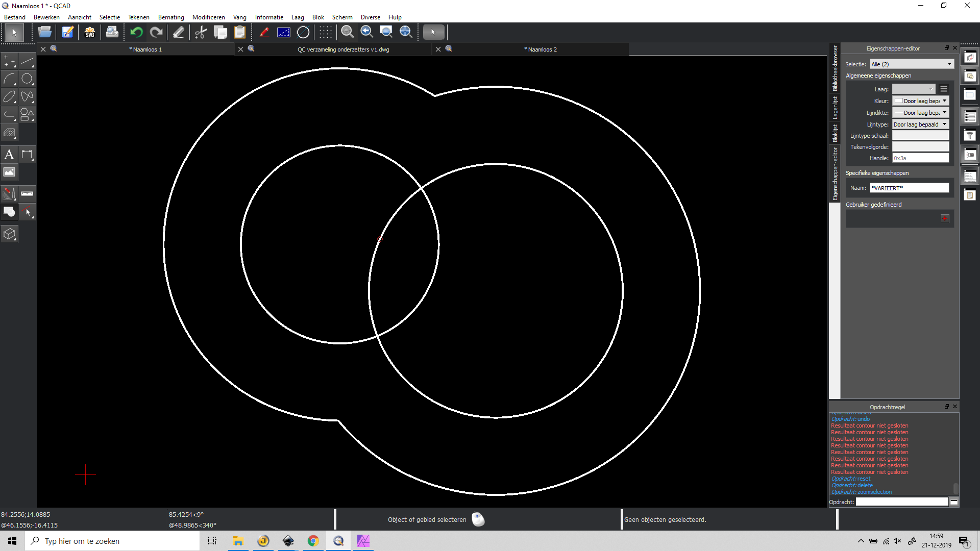
I tried another way of solving the issue. In the picture is seen that two circles with offset distance deliver a nice result. When I try this with 34 elipses it doesn’t. My idea was to do it with the offset tool and then make an inner offset line as well. That one should then correspond with the orginal form of the 34 elipses. Next time I tried with 4 elipses it crashed.
Can you attach an example that crashes? Does it really crash or just hang, i.e. the operation takes very long? Note that if QCAD is “not responding” that does not mean it crashed but simply that it’s busy.
OK finally I found a way to realize it. The critical mistake was that I accidentally scaled the group of entities in Inkscape. So I tried everything again and then it finally worked.
So in short description:
Export to Inkscape with advanced svg export
In Inkscape everything disapeared, set linewidth to 0,1 and the lines appear again
The import from Qcad is twice grouped: Object > ungroup > 2x
copy all lines to keep the originals (just to be sure)
select all lines: path > unite
The result is exported as dxf r14 lwpolyline selected
Imported in the qcad drawing
select the lines and convert to polyline by ‘polyline from segments’ (OG)
a little scaling was needed: modify > scale > by mouse (choose in dialog)
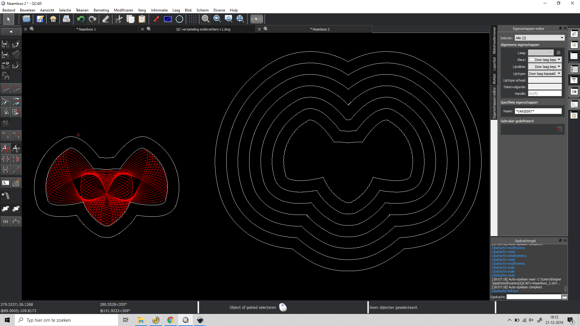
Result in the image
Afterwards the offset tool (offset with distance) worked fine
So for other users who want to perform tricks like this, this is a way to do a boolean operation nice and pretty easy if you follow these steps.
@CVH Did you change the elipses into polylines first? What function did you use for that? I still feel like a greenhorn in Qcad, but getting more used to it day by day.
I ordered the qcad-book on lulu, but it is little delayed by christmas madness.
@Andrew: The crash did happen, but I couldn’t reproduce it. It might be something like I was impatiened and doing too much at the same time. Nonetheless here is the file that I finally made with Inkscape, perfect result in the end. I’m still curious how to do this within qcad because that is obviously my goal. The closed white contour is made in Inkscape, the second is an offset in Qcad.
Is it a good idea to make a proposal for a uniting boolean tool? This is by far the most used variation and maybe almost there by the offset tool. Or maybe is a handy workflow of the offset tool allready good enough?
Selection → Modify / Explode
But in the end there is something limiting in offsetting a multi selection off polys.
Will file a bugreport.
It’s a long way around. Left - Right - twice selecting where to offset.
It doesn’t come out perfect also due to the limited approximation.
Used 64 segments to explode the ellipses.
Further, an offset of an ellipse is never an ellipse itself.
Offsettting non-ellipses back or one further and two back is never ellipsoid.
Flaws add up.
Very convincing result CVH! Now i see how to do this easy within Qcad. I’m still curious wether it is a good idea to propose a new feature with one or a few boolean functions. On the other hand, this is the ‘brainpower method’ as Husky stated. Thanks for your help!
The quote of Husky was made in a basic tutorial on youtube. It was a funny quote so I remenbered it.
Last question for the moment: you said the elips was divided in 64 points in a polyline. When I repeated your action, it made only 32. Do you know where this can be ajusted, or is it in the program preferences?
I still have issues combining polygons with offset. See these results in the images. Maybe I do something wrong but I can’t find out what it could be. 3 polygons are selected but only 2 want to offset. Is there something to prevent this? In the case wilt elipses there were 4 of them perfectly combined?
Offset off multi selections migt be troublesome.
Clipping or not may differ a lot.
There are 4 methods:
Poly offset OQ
Selection offset OF, OH
Misc/Draw/Poly Alternative
It might that an other method has better outcomes
Like I said, do this a lot.
Posted on it a lot.
A few problems I could let resolve already.
Complaining is easy, isolating the problem is not.
eg. See:
and related forum topics
Nobody else seems to have troubles with it!!!..???
Or its called expected behaviour.
Proper offset are a base for good CAM outputs offsetting!!?
Divide your problem up.
Offsets
Combine Offsets at your discretion.
I’m sorry to replay so late, I was away for a few days. Today I copied the file to make it ready to post here. The original drwawing is altered, and now the problem disppeared. (?!?) So I can’t reproduce it. Next time I will post the file immidiately after a problem occurs, this is strange and frustrating, the screenshots were made of results and not of preview. I tested it several times before making my post. But anyway I can’t reproduce it…
Last post the unexpected results were not easy to reproduce. Now I got a new file with the same kind of results as the first.
In both cases my design was made with a lot of elipses. The advice of CVH was to convert the ellipses into polylines. The collection polylines was selected to make an offset as a workaround for boolean functions. The idea was first to make a offset and then reduce it with the same value so a contour will be made.
CVH made allready a bug report so this file can be used as illustration for the bug. A further description is made within the file. Personally I see this surely as unwanted behaviour. No contour is made, there is no usable result at this moment.
The offset method used was OF.
This is a hobby-project and I finished the contour in Inkscape as before, but of course this takes much more time and it would be nice to do this in Qcad. strange results for offset.dxf (1.58 MB)