How do I round two parallel lines which intersect another line, so those arcs for parallel lines ends at offset

How do I round two parallel lines which intersect another line, so the arcs for the parallel ends at define offset to the intersecting line? For example 3 units away. The problem is the arcs are two different length of a unknown value. So I am not sure how to do it rather than just go by .00000001 at a time for each arc with the rounding tool. Which takes for hours basically. So Is there a faster way?

Example is with the picture

Hi,

This is a geometrical problem.
Solved geometrically or by Math (Mathcubes :wink: )

Knowing that:

  • The center of any rounding lies on the angle bisector of two lines.
  • A rounding is tangent to both line segments.
  • The normal to a circle is 90° rotated in relation with a tangent to the circle at the same point.
  • Any normal to a circle crosses the center.

Draw the angle bisector of the vertical and an angled line (LB).
Draw the normal to the angled line at the required offset (dotted) to the vertical line (LO).
The center of the intended rounding (AR) is the intersection of those two auxiliary lines (blue).


By Math:

  • Sweep = |180 - Included angle|
    Radius = Offset / (1-cos(Sweep))

There is nothing to round when the included angle is zero or 180°
Sweep = zero would lead to a division by zero.


BTW: I prefer to draw on a darker background because the contrast with the line-art is better.
Better for your eyes too.
I used different colors (layers) otherwise everything is blue on white.

Regards,
CVH

Think you alot. I do mean that. I still have a question. Is there a way with LO and tools like it to select an intersection for the position? Or is it like just zoom in far enough and just eyeball the center?

–Deleted–

–Deleted–

If a position is required then QCAD will show the Snap tools in the CAD Tools toolbar, typically at the left.
There you can activate ‘Intersection’ (SI) or ‘Intersection Manual’ (SY) for the position.
With SI indicate near the intended intersection.
SY requires you to indicate two entities that intersect in the long run.
Hints beside the mouse icon in the Status Bar will guide you.

If the CAD Tools toolbar is set to be NOT visible then you can still select the snap mode in the Snap menu.
Or you could activate the required Snap directly with the keyboard shortcuts.

Beside that, typically snapping is in Auto mode what will automatically detect a nearby intersection.
One can configure what is included in the Auto mode.
See menu Edit .. Application Preferences .. Snap .. Auto Snap
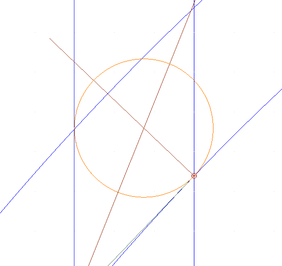
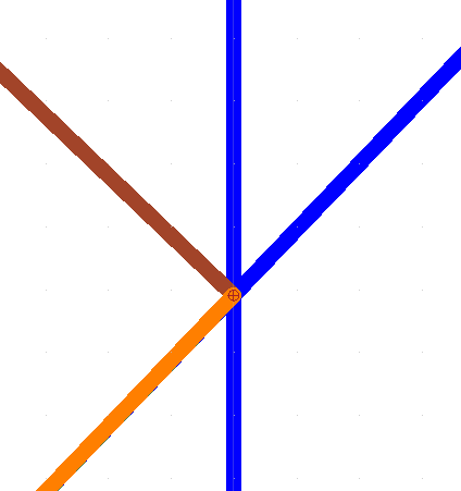
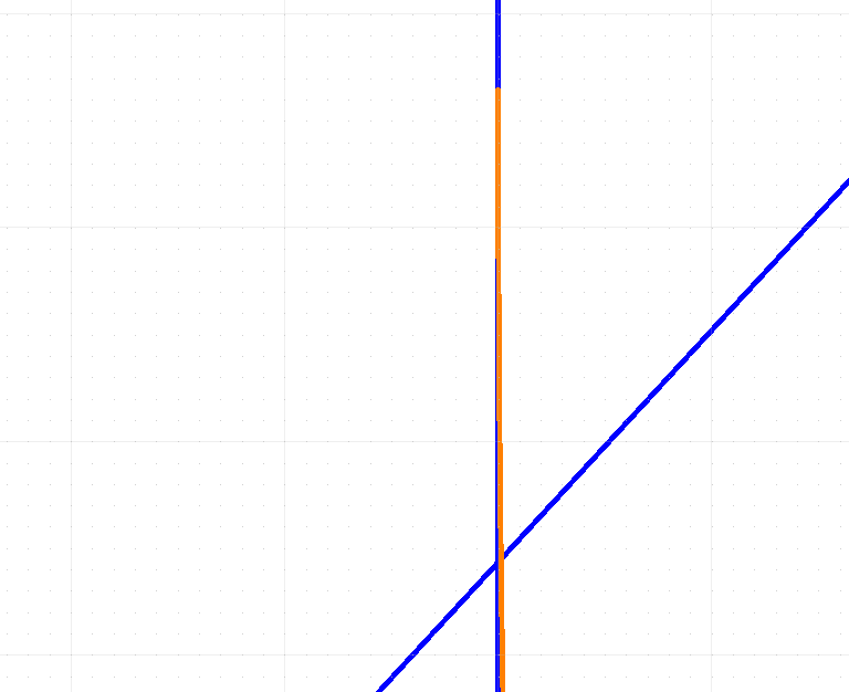
Assure that the cursor snap tip says ‘Intersection’ … Some snapping positions may be close together or coincide.


# EDIT # Question 2 with picture deleted … :unamused:


In your second example the slanted lines seems to be Arcs instead of Lines.
The solution is practically the same but there are (not yet) methods in QCAD to do that.

A screenshot is fine where pictures tell more than words. :wink:
But here I would expect an attached drawing file for knowing the exact details. (See the above forum rules in red)
For some situations there might be an easier route than the exact method below.
We could also fall back on the tangents what is again a Line-Line rounding problem.


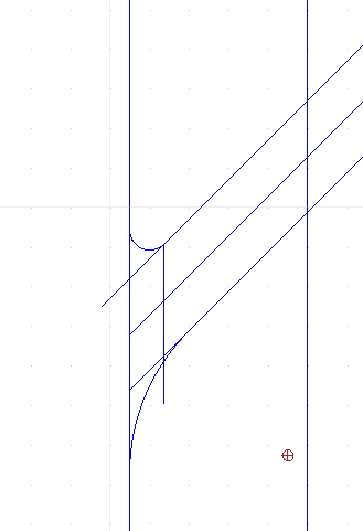
Where the rounding Arc connects to the curved edge is defined by the offset Line (dotted in my case).
Curved edge an rounding Arc are tangentially connected at that point.
The rules for (both) tangent(s) and (both) normal(s) are just the same in the point of contact.
The rounding center will be situated on the normal through that point.

However:
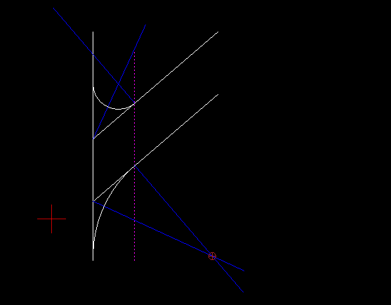
The locus of the center points for any rounding of two Lines at an angle is the angle bisector.
Here a bisector is thus a line of equal distances seen from the two Lines in question.
But the locus of equal distances from a Line and an Arc is a Parabola.

The center of the intended rounding is then the intersection of the normal and the Parabola.

A Parabola can be drawn with the Control Point Spline tool using degree 2 and 3 points, as not closed.
Correct placement of the 3 points is the key problem but perfectly doable.

How correct the intersection of a Spline and a Line is calculated will be a next issue.
This is mostly close enough to be usable. :slight_smile:

  • = - = - = - = - = - = - = - = - = - = -

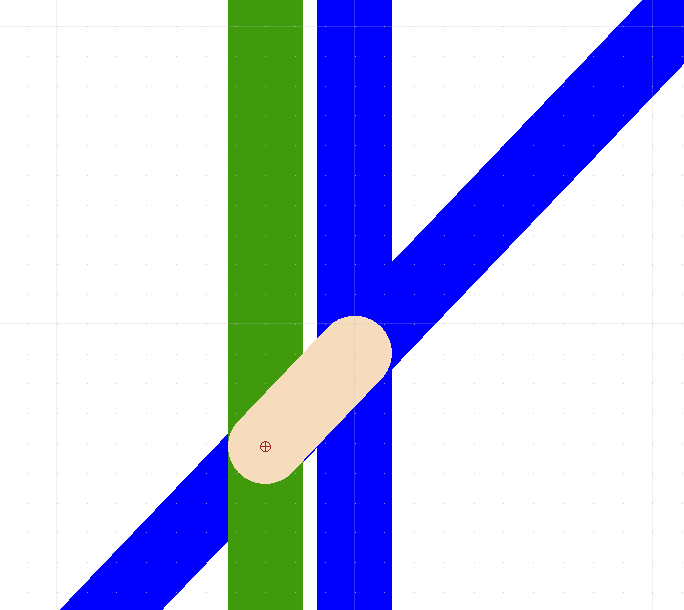
I have a custom tool that draws the locus of equal distances between:
Point-Point, Point-Line, Line-Line, Point-Arc, Line-Arc and Arc-Arc.

Line-Line looks easy enough although an endless bisector is only true for endless intersecting lines.
Where a line segment ends it is no longer a Line-Line case, instead it is a Line-Point case.
And beyond the end of the other line segment it becomes a Point-Point case.
All very similar with a limited Arc-segment and its endings.
But then:
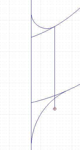
For Arc-Arc not tangentially connected the locus would be a Hyperbola.
Did not find a good method to mold a Spline to mimic such a Hyperbola shape.
Basically a limitation of the Splines supported by QCAD.
For now it is an approximation based on 12 trial points.

Not correct enough in my book and thus unfinished or not ready to propose the tool as an addition.

Regards,
CVH

Yeah I just figure that out. Hints why I deleted it. Um, at the limit of the curve just draw a line segment toward the base with it being like .0004 on the curve then just extending it outwards towards the base and just use that. It’s like almost spot on that if I zoom in the lines are thicker than the gap.

It’s within the preciseness of qcad with .00000001 pension. It’s slightly off but that’s where it places the intersection with a bisecting line. Granted, if you zoom in far enough see things will be misaligned naturally but after so many decimal places sooner or later you are just going to be on the atomic scale anyways so it doesn’t matter.

PS. This method took me like 7 hours straight with a trail and error approach.

A very rough approximation.
As you mention yourself, it is not connected, not tangent, … It only looks like that.

QCAD has no method to draw the tangent to the curved line at the intersection with the offset (dotted)
But you can exploit ‘Line Orthogonal’ (LO) twice.
The tangent and the normal are 90° rotated and are orthogonal.

LO, indicate the curve (L-click), and the intersection with the offset (L-click).
Back (R-click)
Indicate the normal entity just created (L-click), and the intersection with the offset (L-click).
Handle it further as a Line-Line case as in the initial answer.

You will end up with the intended center of the rounding.
On the normal to the curve and as one point on the mentioned Parabola.
Meaning that you can solve this for a unique case.
Solved as utterly correct without ‘guessing’.

Regards,
CVH

I can hatch it so to qcad it’s connected

Being connected is within a tolerance.
The boundary is simple forced to be closed.
And that in a manner beyond your control.

The Hatched area ends at the vector art what has no thickness.
Surrounding entities have a Lineweight and will mask any incompleteness.

Regards,
CVH