I know how to do it in Adobe Illustrator but I don’t know how to do it in QCAD.
How do I make a dash line that doesn’t change base the thickness of the zoom I am viewing it at. For example I want a line that is 4 inches in width FIX base on the dawning and a dash of like 8 inches and a gap of 4 inches repeating? Like how do I do it without the pain sneakingly of drawing out every dash and putting a solid hatch in each one? I am doing a project of hundreds of dashes and I am really not sure how to do it.?
I can use the paste along path tool pe. But how do I make the rectangles curve to the path instead of being flat and majorly sticking out. Like an offset?
First, in CAD there are but a limited and fixed Lineweights from 0.00mm up to 2.11mm and these don’t scale with paper scale.
It are the historic pen sizes from the time we drew directly with ink on paper.
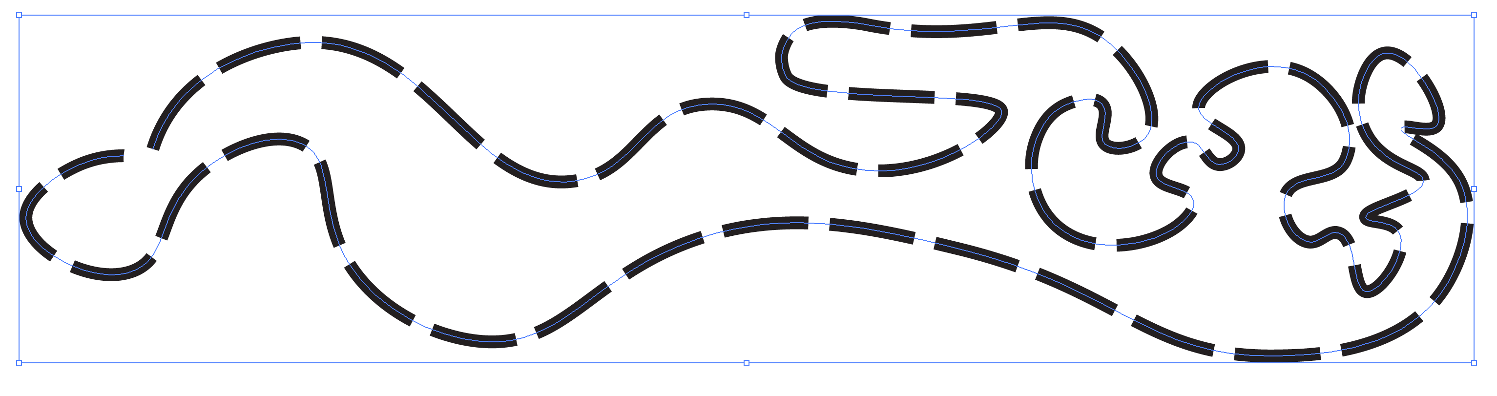
This line-art uses round ends … As if a round pen
It is possible to have polylines with an arbitrary global or local width.
This line-art doesn’t mix with Linetype and it uses squared off ends … As if a flat pen.
4 units (inch) wide is an option but it will not be patterned.
The only direct metric solution I see is the paper scale.
When for example the scale is 1:20 then a 0.20mm line would represent a 4mm wide line on paper.
But there are no inch based Lineweights so the scale would be something weird to represent 4 inch.
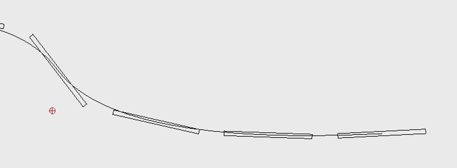
Another solution I see is Paste along Entity (PE):
Draw the contour of your dash of 4 units wide and 8 units long and hatch that.
Copy these or only the Hatch with reference (RC), use for example a middle point at the start as reference.
Paste that over an auxiliary center line entity opting for Distance = 12 units.
Hide or delete the center line.
This won’t be perfect at corners, at the end or along curvature for Polylines or Splines as base shape.
It won’t be perfect along Arcs or Circles or for the last item over any line-art.
But it is a start with far less editing to do in a later stage.
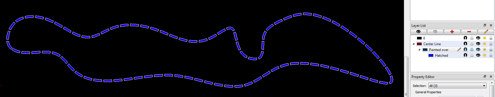
Another solution is a custom QCAD Pro tool called FlexPainter (FP) (… LineTypes on steroids ).
Opt for the ‘QuadrilateralFlexing’ painter set and enter the required sizing and other options.
As is included in a standard installation it doesn’t support fills yet, sorry .
Cast them on a dedicated sub-layer.
Select all on the sub-layer and hatch those as one.
In the light of the changes you made to your topic meanwhile … Then the latter is your best option.
The displayed weight and type (width and dash/space) will only be dynamical when using Screen-based Linetypes (NL).
If you clear that option then the line-art is displayed ‘As is’ … In any zoom state.
Vector art size will never be fixed in any zoom state.
It will be larger on screen when zoomed in and smaller when zoomed out. e_geek
Except the display size of a Point because that is pixel based.
A vectorized point has no dimensions and vectors have in fact no width, only line-art does.
Screen-based Linetypes are a displaying hybrid because screens have a far worse resolution than printers for example.
Using Screen-based Linetypes it will always look somewhat thick/thin, dashed/dotted in any zoom state.
Zooming too far in on a 1mm line without Screen-based may fill whole the screen.
And when zooming too far out the space between dashes may decrease to less than half a pixel making it look like continuously.
Or the line may become so thin that it is less than a half pixel and disappears from the screen.
This last is captured and the minimum is 1 pixel.
By default Screen-based are turned off for printing or exporting to PDF for example.
Although, all is configurable by preferences.
On the other hand …
A dashed line width of 2 meters looks more like details we would draw separately instead of representing it with a single patterned line.
And a gear must already be huge to implement it in 4 inch dashed line-art.
A gear painter for FlexPainter is out of the question.
It will never be precise enough and matching tooth geometry on any arbitrary base shape except lines, arcs or circles is practically impossible.
… Or at least not that straight-forward.
But yeah work smarter and not harder. The more which can be automatic the better. It’s like drawing a rectangle in one go instead of drawing 4 lines individually.