This is something I have also found a bit confusing. The following is perhaps not so much a direct answer but some insights (or lack of …) in regards to line-type scaling.
My understanding of how it is supposed to work is illustrated below with a simple centerline pattern and how it appears in model-space, print-space and print-space and cahnges depending on viewport setting and linetype-scale setting. All images scaled to the same apparent screen size (roughly).
If we start with a linetype-scale of 1 (default) the model space looks like this.
If we view this with “Screenbased-linetypes” it is almost the same
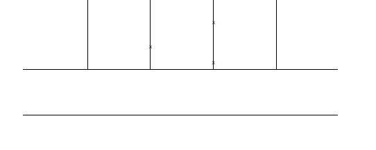
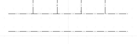
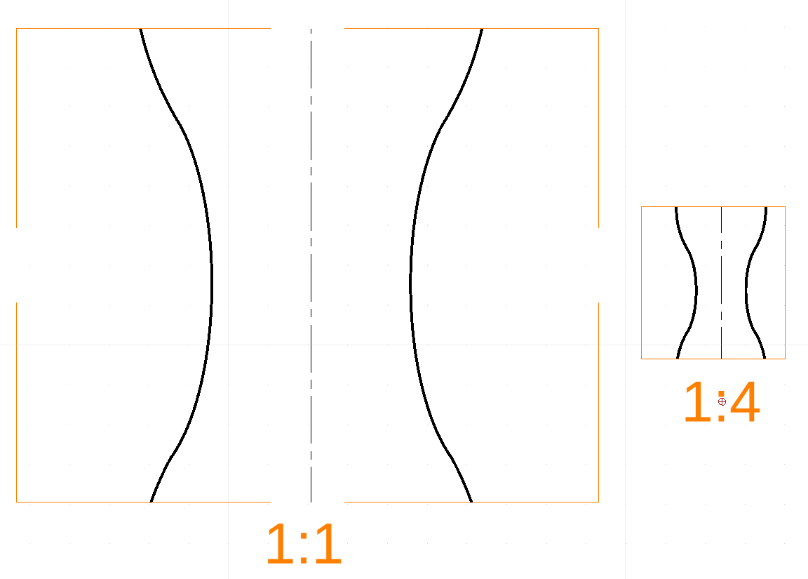
If we then disable sceenbased-linetypes and put this in the paper-space in both a 1:1 and a 1:4 scale it will look like below
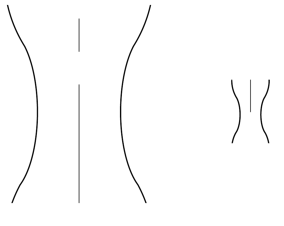
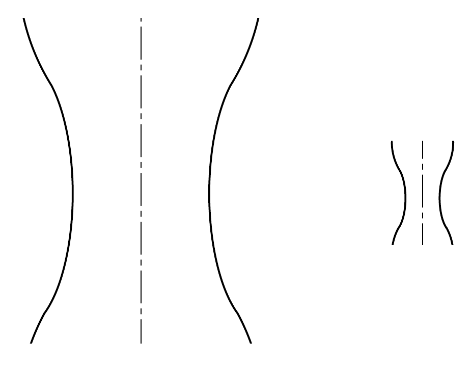
Exported to PDF this will look like this
If we instead repeat the previous exercise but with the option
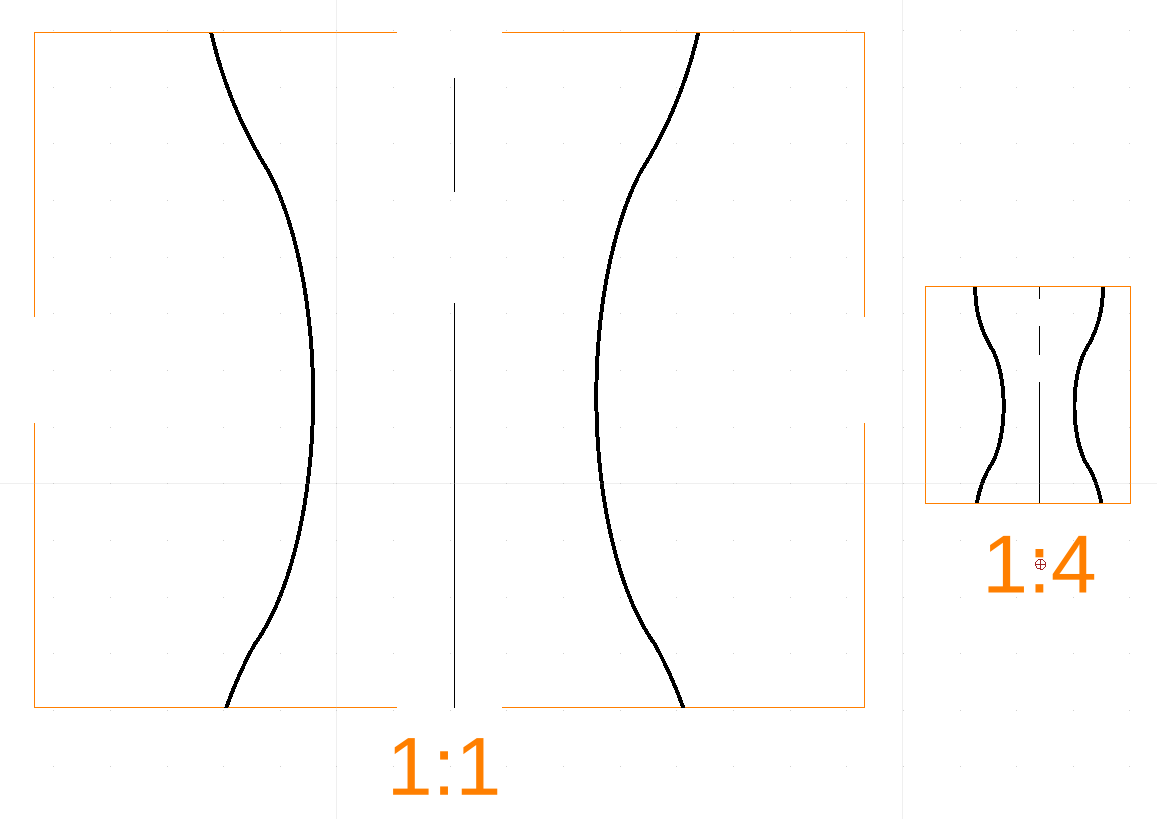
“Scale of linetypes matches the scale of the viewport” checked (Preferences->General->Linetypes) we get the following (the model space is not affected by this!)
Paper-space:
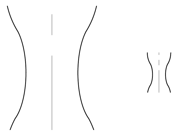
As we can see the 1:1 viewport is the same but the 1:4 viewport has been adjusted. In PDF it looks like expected
Changing the linetype-scale
In prints I prefer to have more tight lines so I usually apply a factor to the linetype scale and here things become interesting. The model space and print space does seem to start behaving in what might seem different ways. If we apply a 1/10 scale factor (0.1) the result is as follows:
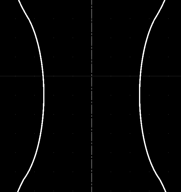
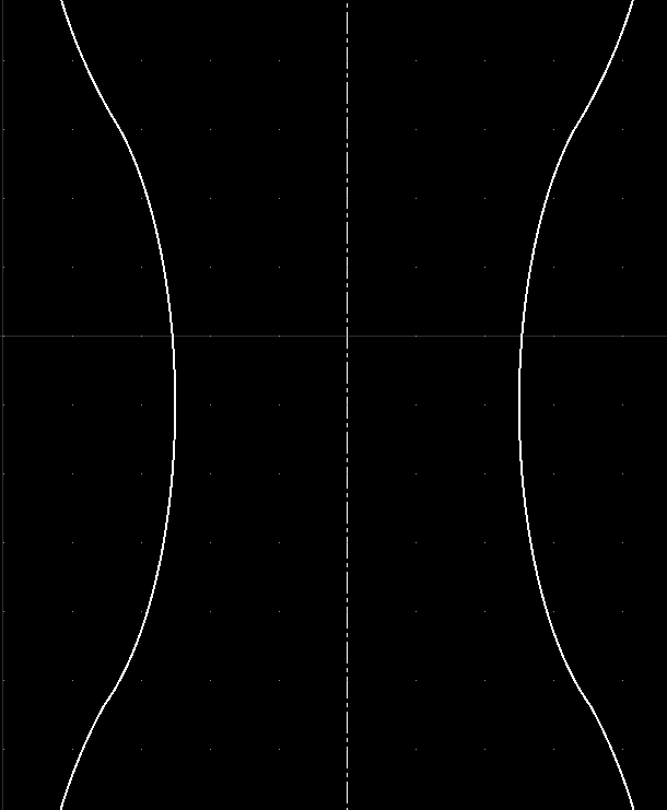
First the model space
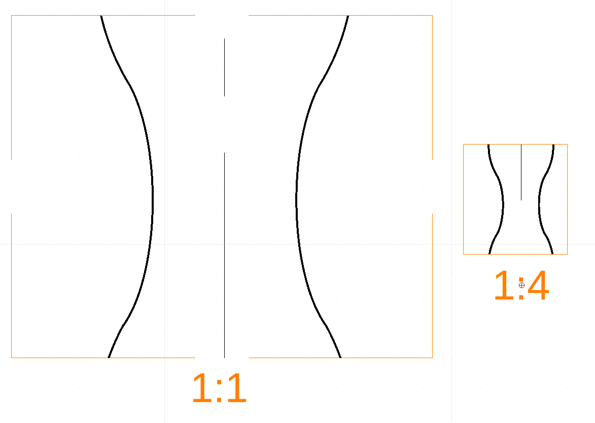
With this scaling we are no longer able to see the individual gaps in the line. However …the paper space looks as expected
whish is also reflected in the resulting PDF
If we now again check the
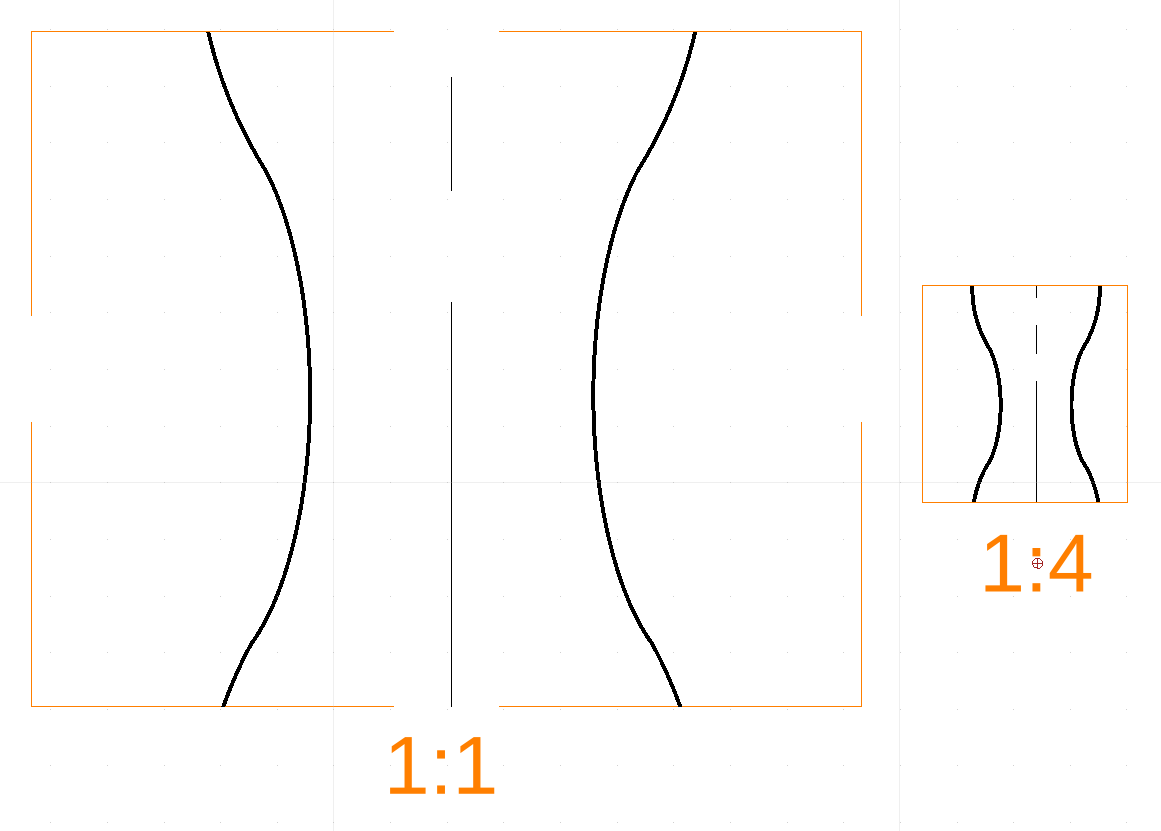
“Scale of linetypes matches the scale of the viewport” The paper space will become
This result is unexpected. With the default linetype scaling of 1 the (1:4) scale in the previous example got a bit denser (don’t think it was four times though) bu he we actually get a less denser line! Which I cannot quite explain. My understanding of viewport scaling of linetypes is that the should follow the scale to appear the same in absolute appearance which clearly is a wrong understanding o my part..
My understanding was that the dashed lines should follow ISO absolute lengths However the above experiment shows this not quite to be the case since the model-space and print-space with the same 1:1 scale shows different density for the dashed lines. The print space (for center-line) shows a gap of 20mm while the model space shows a gap of ~0.6mm .
I’m sure I must have misunderstood something and since I can always workaround by manually setting a linetype-scale (to get the proper ISO spacing in the final PDF output I’ve just put this as on of life’s (many) mysteries!