I really like the projection tools and the Isometric grid to create Isometric drawings.
However, I have not been able to find out how to add text and dimensions that would look correct in
these drawings.
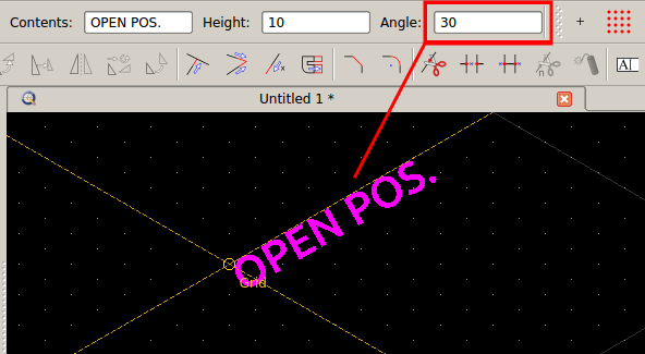
In autocad, I used Oblique angle for the text properties and rotated as required. What shoud I do here?
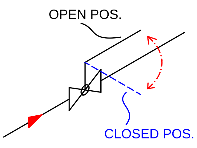
For reference, see my example drawing below. I would like the text to follow the isometric lines and perhaps
add dimensions showing the length of the pipe line.
I see what you mean. However, this is not correct for annotating isometric drawings. The numbers do not have the “correct” isometric perspective.
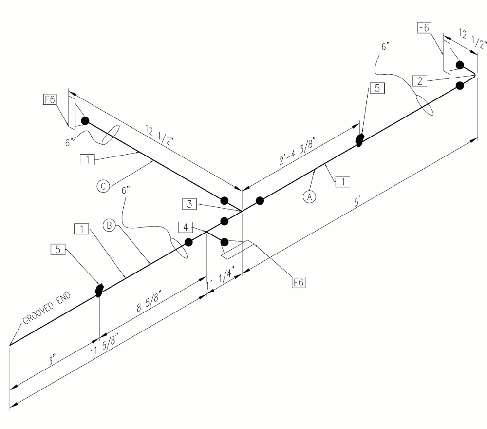
To see what the end result should look like, see the pic attached below which show dimensions placed on an isometric piping drawing. Text and dimensions
have to be placed horizontally, or vertically with the proper isometric perspective and orientation (you can google more examples if you wish to do so). So far, I have not found a way to do this in Qcad.
ps In this example the annotation “Grooved End” follows your solution but it is not correct.
@andrew yes that would work but it would require me to draw every pipe run in front view first and the project it. Moreover, the dimension gets exploded once it gets projected ie it can not be edited.
In my field of work (I am a piping engineer) we use the isometric grid to draw our piping layout and then add annotations (dimensions, text, etc) as necessary. Doing it otherwise would complicate things
greatly I am afraid. Same would go for mechanical parts as well, I imagine.
I understand. The isometric tools of QCAD are not really suitable for drawing directly in isometric space.
They are rather meant to produce an isometric drawing once the top / side / front views have been drawn already.