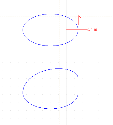
Is there a built-in way of stretching an ellipse with one cut point into a “corkscrew” ? The stretch function doesn’t seem to be able to do that.
The arrow is perpendicular to the ellipse’s plane
I don’t see how this would be mathematically defined.
Perhaps a spline is better suited for what you are trying to do?
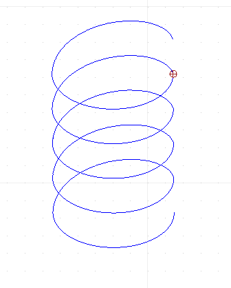
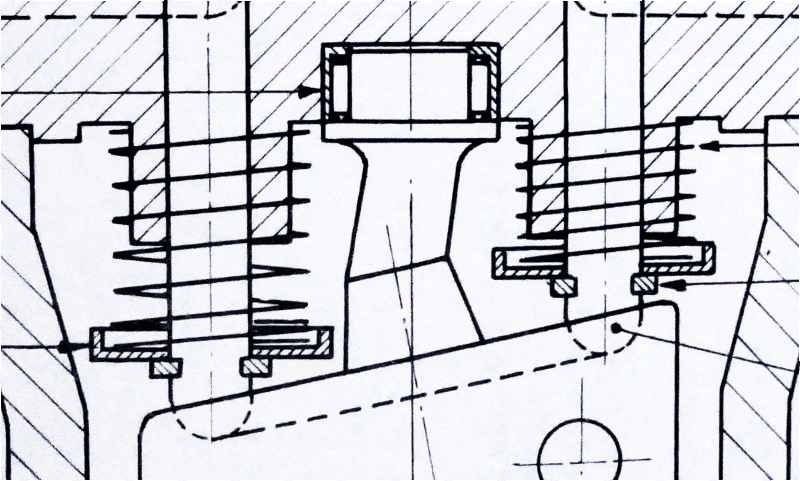
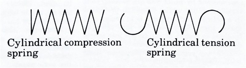
I have faced that problem when drawing schematic symbols of coils and transformers. The 3D view of a helix is exactly what is generally used for the coil in these drawings. It is easy for a rough helix to be drawn by hand, which is probably why they are used - grandfathered in from the old days, so to speak. But I have used about a half dozen 2D CAD programs and none of them, in my memory, could do this accurately.
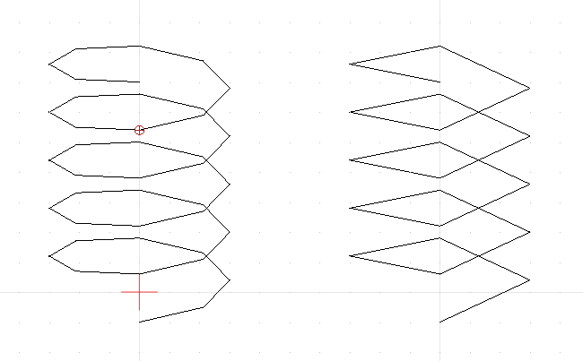
My work-around is to use two arcs, about 90 degrees each and connecting them at one end, sort of football shaped. The other ends are stopped somewhat short of actually meeting and the next “coil” is attached with those points so each coil (pair of arcs) is offset from the previous. This was good enough to get the idea across.
I guess you could replace the points of joining with more arcs with smaller radii (chamfers) if you need a better approximation. This would be sort of like the old manual drafting method of approximating an ellipse with four arcs. It ain’t perfect, but it can look nice. Of course more arcs adds more size to the part so it’s a compromise.
Another way, which would probably be a lot of work, would be to create the helix in a 3D CAD program and take a screen shot. Then import that screen shot into QCAD and either just use it or draw over it with splines or whatever.
Already looking far better. ![]()
Although it is not a Helix or Corkscrew in perspective …
The approximation by an ellipse is fairly logical because a winding is about a circle an in perspective that is an ellipse.
The rather short arc is a nice replacement for yet another part of an ellipse.
Together it will yield a good approximation at low rendering calculation costs.
Nice ![]()
Now I wonder on how good the approximation is.
Would you want to consider to share your design within a drawing file?
I expect that the curvature should differ for the far and the near part while that is symmetric in your case.
Regards,
CVH
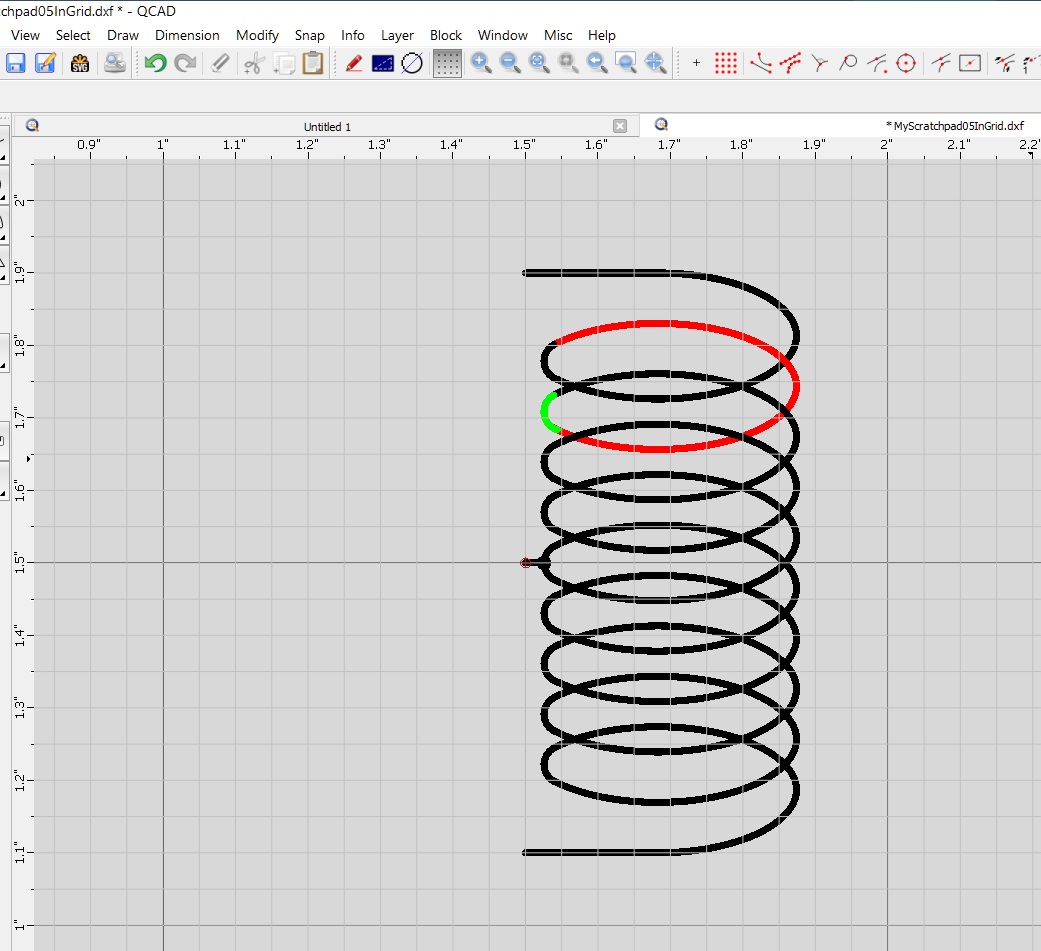
I am attaching the file for that helix part.
I had a bit of a problem making it and a compromise was necessary. That was good enough for my purpose which was a nice looking schematic symbol. Accuracy was not really necessary. As you know I am a QCAD newbee so perhaps you know of a way to do that I could not find.
Drawing and removing a part of the ellipse was trivial. I simply drew a vertical line and used the Break Out Segment command in the Modify menu. But I could not find a way to precisely draw an arc between the end of one ellipse and the opposite end of the next, making it tangent to both. Ideally I wanted to specify the middle point of the arc, but that would have been greedy. I tried the Tangent restraint but could not get it to work. So I just zoomed in tight and drew the arc by sight. Then the Trim Both command, also in the Modify menu to have the arc and ellipse meet at a point. It came out great looking, but is not precise even for the use of an arc for the approximation to the helix.
If by “far and the near part” you mean the top and bottom ends of the helix in my drawing, then the partial ellipse and the arc are exactly the same at both ends. I did not make any effort at true perspective. It is only a nice looking symbol.
And YES, I was trying to avoid elements, like a spline, that would require excessive rendering time. This helix will be used in a number of schematic symbols and more than one may be on a given drawing.
CoilWithCTVert800.dxf (102 KB)
Indeed kinda problematic and remark that the lower part of your little arcs ‘overlaps’ with the ‘next’ ellipse arc.
The solution is drawing a normal or tangent at the intended (end-)point on (of) the ellipse (arc).
Steps are visualized in the attached file each on a separate layer, just make them visible one by one for stepping trough.
I added ‘Far’ and ‘Near’ on an extra layer. ![]()
HowTo_ArcTangent2ptOfEllipses.dxf (102 KB)
When non-symmetric one needs to construct both normals in both endpoints and use CT2 ![]() .
.
Regards,
CVH
I neglected to mention that I was also trying to give the finished “helix” a given width. So the mid point of my arc would need to be at that width from the opposite side of the “helix”. I drew the “helix” as part of my collection of electronic symbols and wanted to keep things on a grid. But in the end, after scaling for the vertical distance, it would up off-grid anyway.
Of course I knew that perpendiculars to the ellipse ends would result in a center for the arc for the tangent condition. But then the mid point of the arc would fall where it may. Now that I look back, I could have constructed the arc as you describe and then use the scale function to bring the width of the resulting “helix” to the value I wanted. In fact, being the perfectionist that I am, I will probably go back and do it that way.
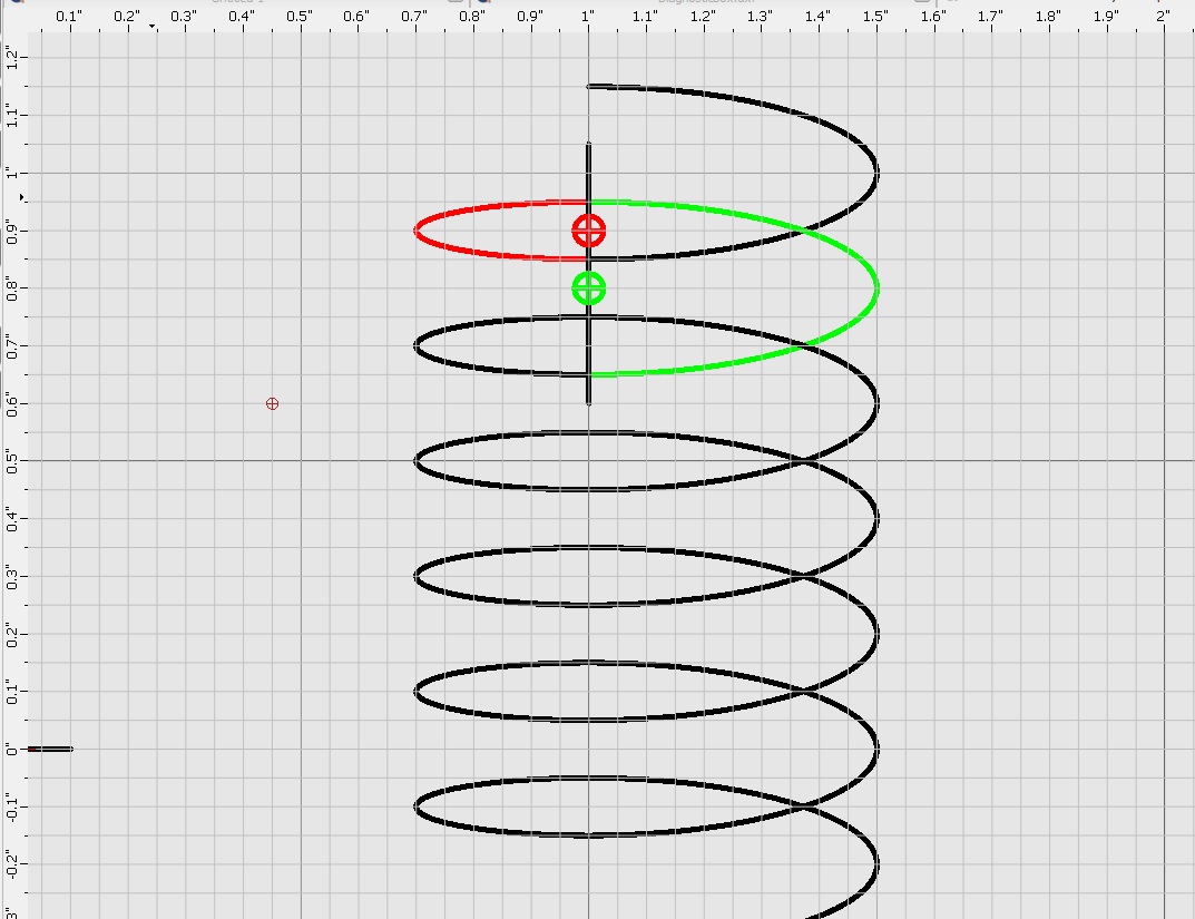
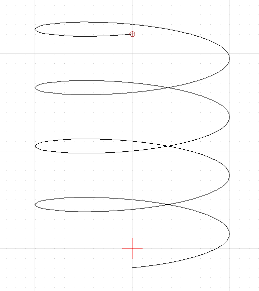
I finally got back to creating my electronic symbols and the coil (a helix) in particular. I was trying to get one that looked better and it seemed to me that the arc that I used previously would look better if it were stretched out. In other words, an elliptical segment. But that would making two elliptical segments meet tangentially. Here’s how I did it:
This produced a very visually pleasing pseudo-helix. And the trick of having them meet on their center lines took all the difficulty out of keeping them tangent.
My next step will be to add horizontal lines for the connections and use X-Y scaling to bring the overall size in agreement with my other symbols while keeping the connections on a 0.1" grid for easy drawing of the connecting wires.
Again looking better, more natural … Nice ![]()
Far/near comes out better too this way.
Using a second ellipse arc is again logical and of course always neater but it increases the rendering efforts.
Regards,
CVH
My desktop computer is around 10 years old and wasn’t anything great when I bought it. It does not seem to struggle with one or two of these “helices” in a drawing. But that proves nothing.
It would seem that there are three choices for this: circular arcs, elliptical arcs, and splines. And all of them must be drawn with straight line segments, each of which takes time to generate and display. I assume that a circular arc, when stretched, becomes an elliptical arc.
Any thoughts on which would render faster? And would different processors change the relative ranking?
Just wondering.
No, 1 or 2 proves nothing. ![]()
I presume in the order of complexity:
Lines - Arcs - Ellipses and then Splines with increasing degree 1,2,3, … with increasing number of points.
Although that splines in degree 1 are nothing but straight segments but they are based on polynomials. ![]()
It will also matter how large the curved shape is and thus with how many tiny straight segments it is rendered.
Ellipses should require more effort because one can only solve them with elliptic integrals or infinite series expansion until converging.
Rather much more complex than simply stretching. e_geek
But series expansion is only partially implemented by me in 2D Centroids to be utterly correct for the ellipse (arc) length.
In general QCAD exploits less demanding and approximated methods.
Qua CPU I think that only the clock-rate really matters, it is probably not a numbers of cores issues.
Modern CPU chips are all equipped with some sort of FPU core.
I am unaware how blocks are rendered, as each Block Reference apart or as Block and then translated, scaled and painted.
One could test that with adding 100, 1000 or more Block References.
Of A) a Block with N arcs or B) a Block with N ellipse arcs, both of about the same size.
Lagging will increase considerable when each Block Reference is treated apart increasing the number of …
… And there may be a very noticeable difference between a file with case A compared with one with case B.
Regards,
CVH
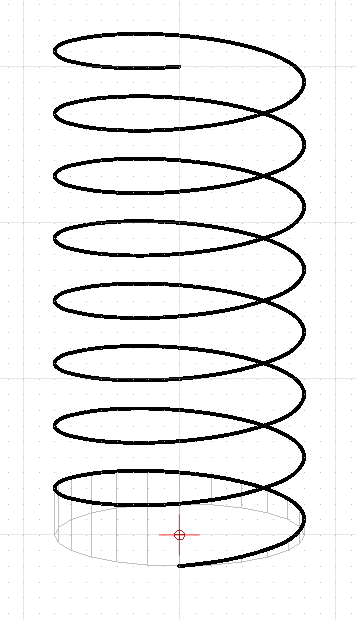
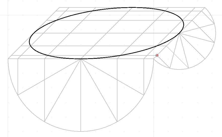
You’re probably happy with your current solution, as it is elegant and visually pleasing, but for anyone who’s interested, here’s how I, as a draftsman, would draw an accurate helix in 3D.
This construction can be adapted for any axonometric or oblique drawings.
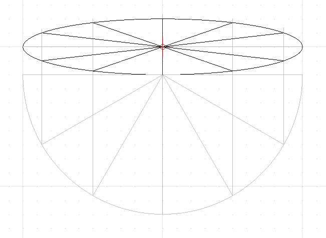
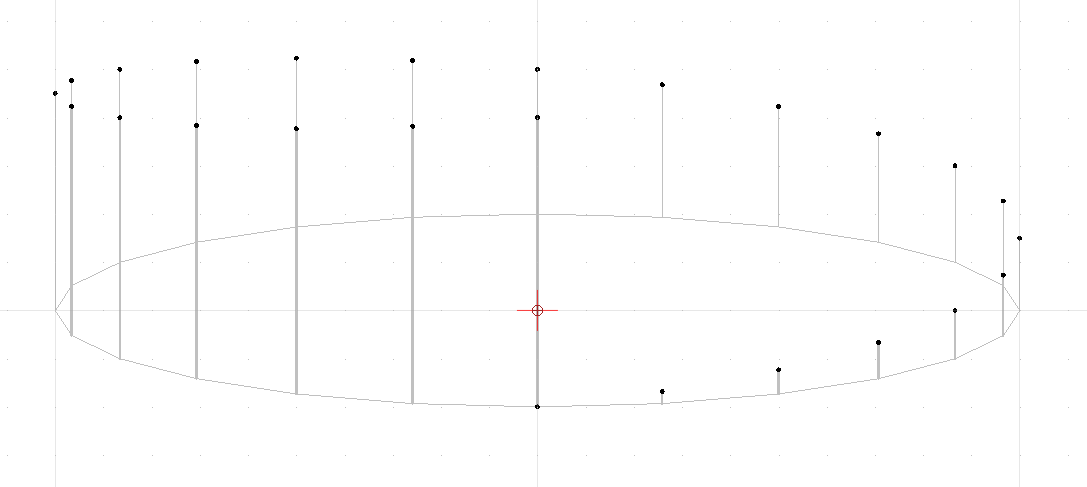
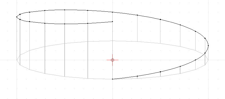
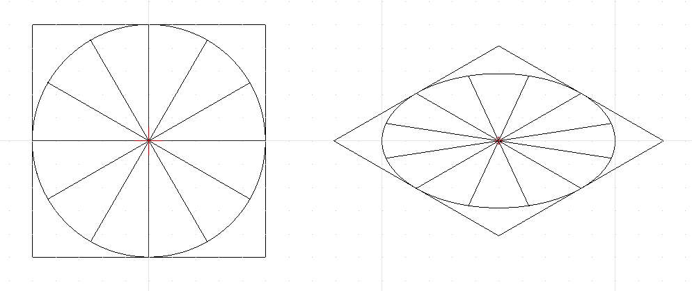
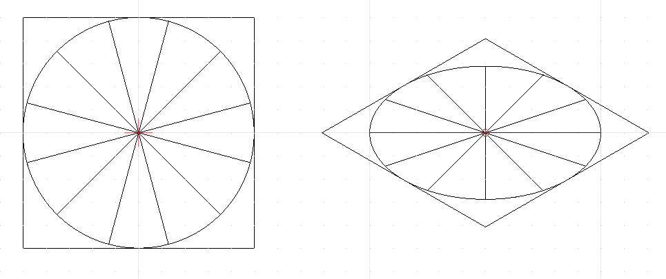
With pencil and paper, I’d draw an ellipse, and find the 12 equal divisions using a 30/60 set square. My ellipse has major and minor axes of 200 and 40, respectively.
Regards,
Derek
And here’s a dxf file with an accurate helix attached, using the same proportions and lead as the last image that Chips&Chips posted…
Nice, thank you …
Probably the best solution up to now. ![]()
You have to admit that what Chips&Chips presented on Feb 29 comes very close visually.
I don’t think that it must be exact for the intended purpose … ![]()
One of the problems I see is that in QCAD splines end normal.
Your start and end curvature is thus not entirely correct between the last 2-3 fitpoints at either side.
Solution:
Overdo it at least 2 extra points at both ends and trim the fit-point spline at the Y axis.
That will result in a control point spline with proper end tangents.
An unanswered question is rendering load.
How much more lag do 8 splines of degree 3 induce compared to 16 ellipses and that for numerous helix blocks inserted on drawing?
And how does that compares with your final spline with 193 fit-points (8x24+1)?
Selecting a 10 by 10 array of such blocks takes about 2-3 seconds on my old Pentium 7.
Some quick test tells me that the spline block is faster … ![]()
Last question:
What type of projection is this?
Your X axis is horizontal and both your Y and Z axis are vertical … ![]()
Regards,
CVH
-Yeah. If I was doing something where I wanted the end tangents correct, I’d add an extra revolution on each end, and then cut them off where I needed.
So if I rotate the circle and lines by 45 degrees first, and then convert/foreshorten it for isometric, The ellipse is identical, but this time I have my construction lines exactly where I want.
edit: Worth noting too, that as I ended up using a circle divided into 24 parts, not the 12 I would use if drawing one by hand, there’s no need to rotate it 45 degrees at all.
Cheers,
Derek