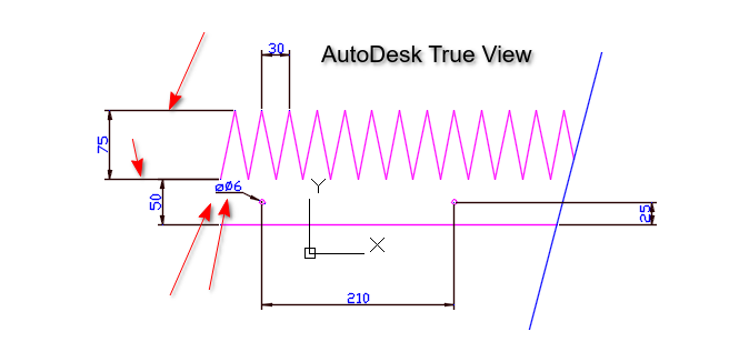
I haven’t come across this before because I usually supply files for profile/laser cutting without dimensions and provide PDFs with dimensions when required. However, a customer requested the dimensioned DXF, and this is how it opened in AutoCAD.
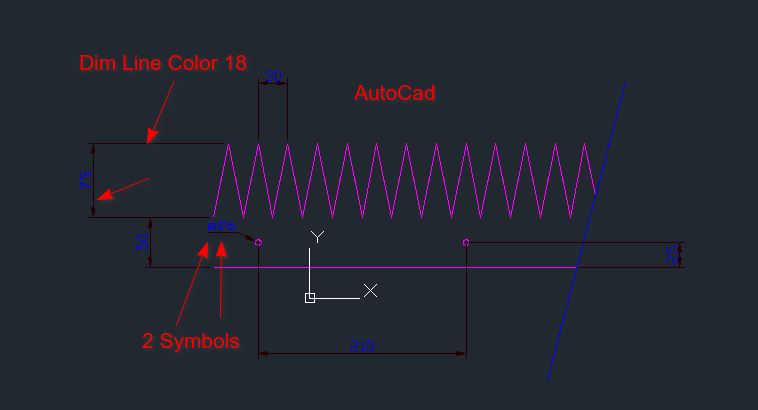
Is there a way to control the “Dim Line Color”? Also, the diameter and radius symbols show twice when I add the prefix. Is there a way to fix that?
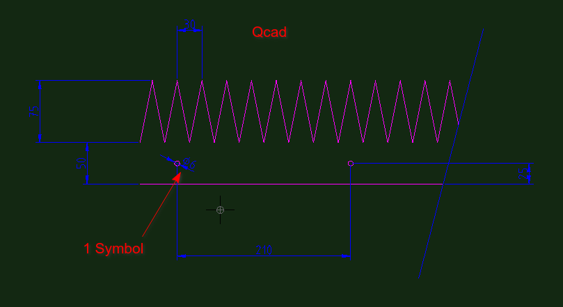
Seemingly a difference between QCAD and ACAD or related.
All Dimensions entities under QCAD are by default without prefix, including Radial and Diametric.
From your observations, ACAD adds a diameter symbol for Diametric to the ‘measured value’ and then ‘ø<>’ results in 2 prefixes.
From the looks of it, the 2 prefixes are in different styles.
One is probably font related and the ACAD supplement is probably from a standard shape file.
Perhaps it is just a ACAD application preference.
Or, it simply can’t be solved from QCAD perspective.
QCAD has less sophisticated Dimension styles, some special formatting or properties are simply not implemented.
All Dimension lines are by the Color attribute of the Dimension entity.
In your case ‘By Layer’ and layer ‘Dims’ is set to blue.
The text color of dimension entity readouts can be set globally in the Drawing Preferences.
In your case ‘By Block’.
By Model_Space block makes no sense so probably just ‘By Layer’.
How does entity color ‘18’ and Dimension text color ‘blue’ work out?
How does entity color ‘18’ and Dimension text color ‘blue’ work out?
I’m not sure where the “Dim line color 18” is coming from—perhaps Andrew could provide some clarity on that?
As for the double prefix issue, it’s not too much of a hassle to work around. You can simply select all the dimensions, set the label to <>, or click the <X “Use auto measurement” to the right option. Then, save the file, email it, and finally undo the changes.
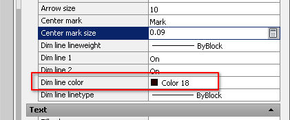
ACAD and related have more control over the Dimension Style.
See example of the ACAD Dimension Style Manager
Color ‘18’ must be translated to RGB values and then use custom color ‘Others…’.
Off-course , but it is good to know that this workaround is required when the receiver uses ACAD.
On the other hand, a prefix for Radial and Diametric is not mandatory.
It should be clear that the indicated measurement is a radius, a diameter or just linear.
ACAD and related have more control over the Dimension Style.
See example of the ACAD Dimension Style Manager
Color ‘18’ must be translated to RGB values and then use custom color ‘Others…’.
I know all about these settings in AutoCAD I used it for over 35 years..
The question is, why is color 18 being used by QCAD? It’s very hard to see on a dark background as well. Why is it even changing? I would have assumed it would stay blue.
On the other hand, a prefix for Radial and Diametric is not mandatory.
It should be clear that the indicated measurement is a radius, a diameter or just linear.
The use of the “R” for radii and the ⌀ symbol for diameters is consistent with international standards, so it ensures uniformity across technical drawings.
Got it.
Intended is ‘blue’ but the result is a dark red color ‘18’ (#4F0000) in ‘the other’ application.
These colors are controlled by a few ACAD system parameters also included in the file: DIMCLRD Color of Dimension lines, leaders and arrowheads (18 in your file) DIMCLRE Color of the extension lines (18 in your file) DIMCLRT Color of Dimension text (0 in your file)
Default value is said to be zero for all 3 (ACAD reference)
Zero seems to work out as intended for the dimension text.
These are ACAD global system parameters, a Dimension can use a custom defined style.
They are listed as ‘Well established document variables’ in QCAD code.
Example DXF files (>800) under the QCAD folder typical use zero, 178 or a mix of the two.
The latest file I created lists the values 0, 0, 256 for these parameters.
Regardless of the file version R24-R27-R32, regardless of QCAD version 3.27.6 or 3.31.2 Win7 32bit
Was your example file entirely created with QCAD
What you could do is create and save a new drawing with QCAD, open it with a text editor and search for ‘DIMCLRD’ … ‘DIMCLRT’.
The sequence in my case is:
$DIMCLRD
 70
     0
  9
$DIMCLRE
 70
     0
  9
$DIMCLRT
 70
   256
  9
Not gonna debate on drawing standards, because there are standards and standards.
In the end it is a designer choice and that can sometimes be a choice between two or more evils.
In QCAD you have the choice to add a symbol, it is not by default.
I then suspect there is an ACAD preference to add these symbols per default.