Basic Pattern Maker [ Windows & Linux ]

Hi All,

Pete and I have been waiting for Microsoft to remove the SmartScreen warning when installing our app. It’s been almost three weeks now, and it seems that many casual developers are facing the same issue. We’re planning to upload the App regardless, but please be aware that you’ll encounter a SmartScreen warning, and you can decide whether or not to proceed with the installation.

In the meantime, I’ve attached a sketch file that you might find useful for creating laser-cut garden screens.
Happy Hatching :wink:
John & Pete


And here’s the BPM sketch file:-
bpm-screen-08.zip (1.31 KB)

Sorry guys, but I spotted a minute flaw that must occur somewhere in the mathematical approach.
It seems that the tile Width = tile Height and both are 48.00 for this pattern.
The signs of N and M don’t matter in the equations below.
The differences are too pronounced to be artifacts of the rounding to 10 decimal digits.


Regards,
CVH

.


.
Bunny.gif
BPM-v1.5.0.png
You can use these ratios to simulate a circular or curved looking pattern.
circle-grid-24.jpg
.
.
Happy Hatching :slight_smile:
John & PeteVick

If you like this application you might like my Basic Hatch Tool see link below:-


Bunny.gif

:laughing: :smiley:


Homer hatch ten million from origin

Hey All :smiley:

Print your own Christmas paper in Qcad :smiley:
.
Wishing you all a safe and happy festive season… :christmas_tree::christmas_tree::christmas_tree:
Happy Hatching
John & Pete :fallen_leaf:
.
BPM Sketch file and png in zipper..
bpm-xmas-santa.zip (7.9 KB)

Hello everyone,

I hope you all had a nice break! :slight_smile:

I came across this screen on TV and thought it would be fun to recreate it using our free “Basic Pattern Maker” application. I’ve attached the zip file so you can add it to your BPM-Sketches folder. The zip includes the image I used as a guide (though it’s not the best quality).
.
BPM-Screen-11-Files.zip (53.9 KB)
.
If you don’t have BPM yet, you can download it from this link:

.
Happy Hatching!

Cheers,
John & Pete

G’day everyone,

Last year, PeteVick and I released a tool called BPM (Basic Pattern Maker) — a lightweight application for creating .pat files for use in QCAD and other CAD programs.

I’ve just put together a quick tutorial using BPM, based on a pattern I spotted on a screen while watching Jurassic World. I snapped a photo of the scene and used it as inspiration to recreate the hatch pattern using our software.
.


.

.
Jurassic-Pattern-Design-Steps(1).gif
While this tutorial is by myself, BPM is a joint project between Pete and I. If you give it a try, we’d love to see what patterns you come up with!

Happy Hatching
Cheers,
John & Pete

Hi John & Pete,
I just downloaded the last version of BPM, thinking I could use the chevron base file in there and probably create my own later. But It seems I have a problem. When I save them to PAT and try to use them, I don’t have the vertical lines. I try to create my own, and I still have still problem. Is there something I missed ? I’m working on the last windows version. Do I do to configure something before using the programm maybe ?
Thanks a lot !

Could you post the pat file you created please. Did you modify the chevron pattern at all before saving, if so would it be possible for you post that .bpmlc sketch file please.

Hi ELLE_Sonny

Hi John & Pete,
I just downloaded the last version of BPM, thinking I could use the chevron base file in there and probably create my own later. But It seems I have a problem. When I save them to PAT and try to use them, I don’t have the vertical lines. I try to create my own, and I still have still problem. Is there something I missed ? I’m working on the last windows version. Do I do to configure something before using the programm maybe ?
Thanks a lot !

I just tried creating one from scratch and also loading the sample BPM-Sketches Chevron file, and both seem to work fine here.
As Pete mentioned, could you please send us your sketch file (.bpmlc) and the pattern file (.pat) so we can take a look?

Also, just to confirm — when you save, do you see the vertical lines showing both on the left and in the middle?

(See attached image)


Let us know, and one of us will get back to you soon.
Happy Hatching,
John & Pete

Hello
Thank you for your feedback.
So, for my first exports, I didn’t modify the basic files at all. I used the (bmplc) files from the folder I opened and saved them directly as .PAT files.
When I saw that I had this error, I tried to create one myself. And then I got a vertical line, but strangely not the ones at the edges.
When I preview before exporting, I get a correct display of what I want, and what a chevron pattern looks like.

I’m going to do some more testing today.
Thanks again :slight_smile:


chevron03.pat (1.31 KB)
chevrontest.pat (1.05 KB)
chevron01.pat (1008 Bytes)
chevron02.pat (1008 Bytes)

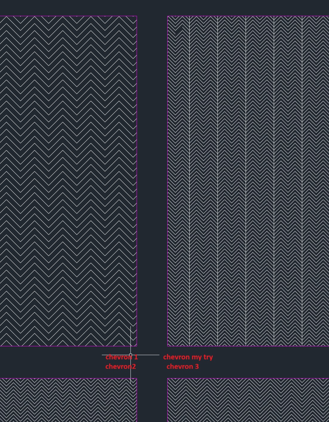
Looking at chevron01.pat - chevron03.pat there is something wrong with how these patterns are coded

e.g. chevron02.pat:

90,2,0,0,4,0,0
90,0,0,0,4,0,0

Both patterned lines are oriented vertical upwards.
The first its pattern starts at (2.0, 0.0), for the second that is (0.0, 0.0).
The patterned lines start positions are repeated every {±0.0 units along the line, ±4.0 units perpendicular to the line}.
So far, so good.

About the pattern of each line, the sixth value and those that follow:
Literally: A dot followed by yet another dot at zero distance apart and that repeated endlessly every zero units along the line.
Essentially this would mean an endless amount of dots on the same position what is a major flaw.

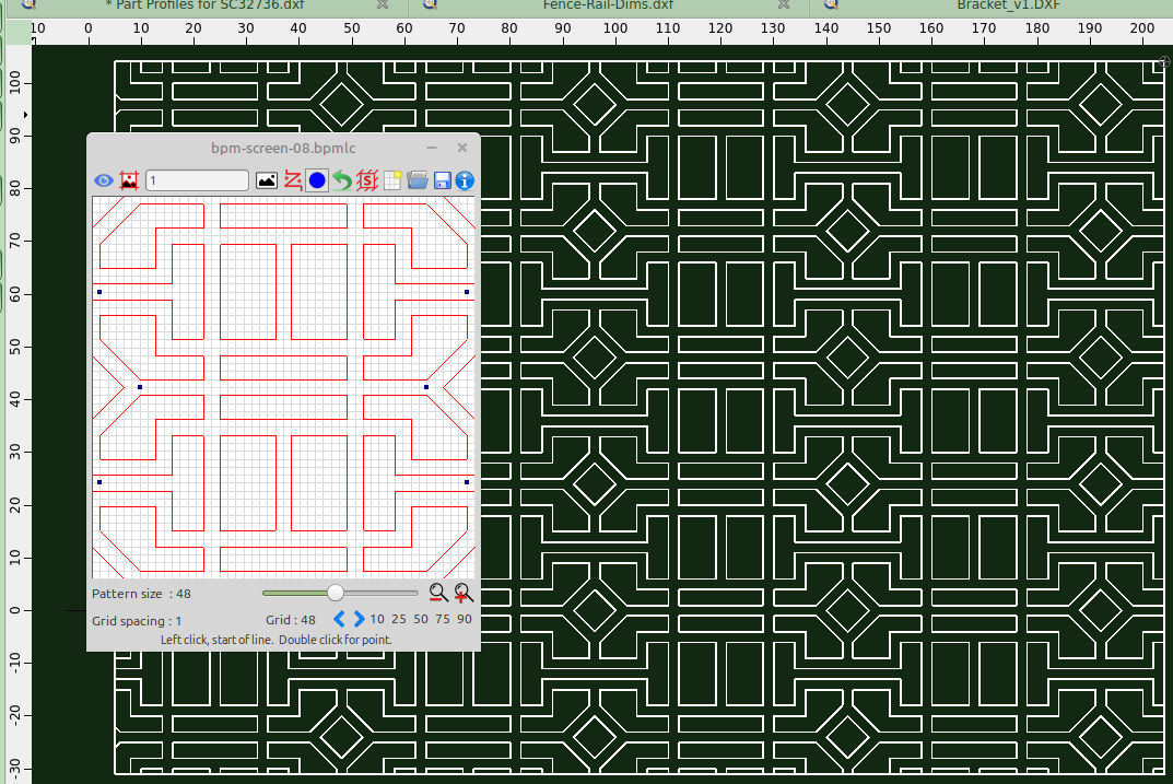
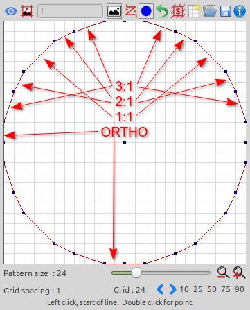
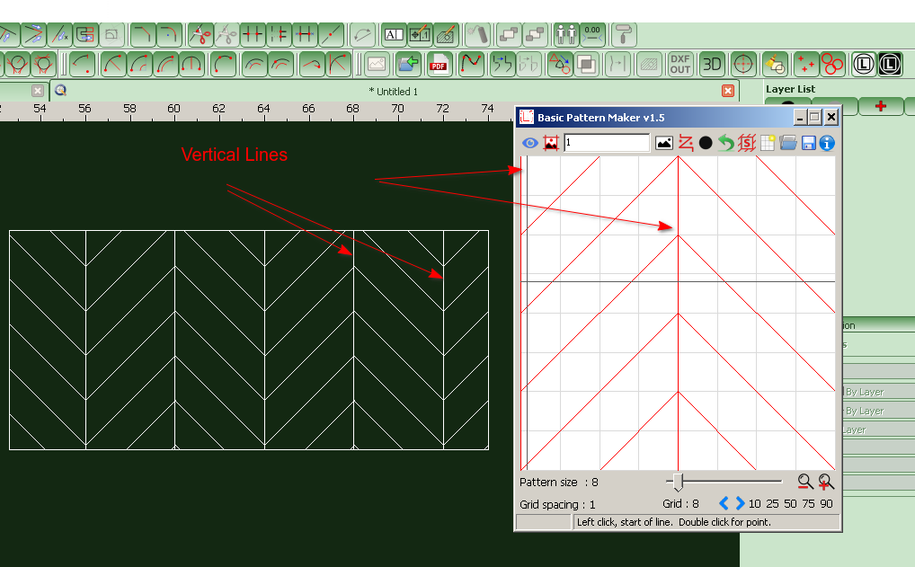
Using QCAD under Windows these are represented by vertical endless lines every 2 units in X.
:arrow_right: 
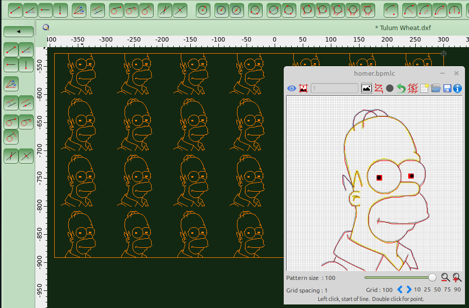
The crosshairs we see in the screenshot do not appear to be QCAD native. :wink:

The complete pattern length to repeat is the sum of the absolute of values #6 - #17 for a maximum of 12 dashes.
These pattern definitions are probably converted by QCAD to XLines because the complete pattern length is zero.
No defined pattern reverts to a not patterned line.


A vertical line every 2 units in X should be coded without dashes as:

90,0,0,0,2

Or as 2 entries but that doubles the work load:

90,0,0,0,4
90,2,0,0,4

A dot is a zero for no length, a dash is a positive value and a space is a negative value.
For repeating dots along the patterned line a zero dash must be followed by the space between them.
e.g. A horizontal line every 2 units in Y with 4 dots per unit along the line:

0,0,0,0,2,0,-0.25

e.g. A horizontal line every 4 units in Y with a dot every 4 units along the line:

0,0,0,0,4,0,-4

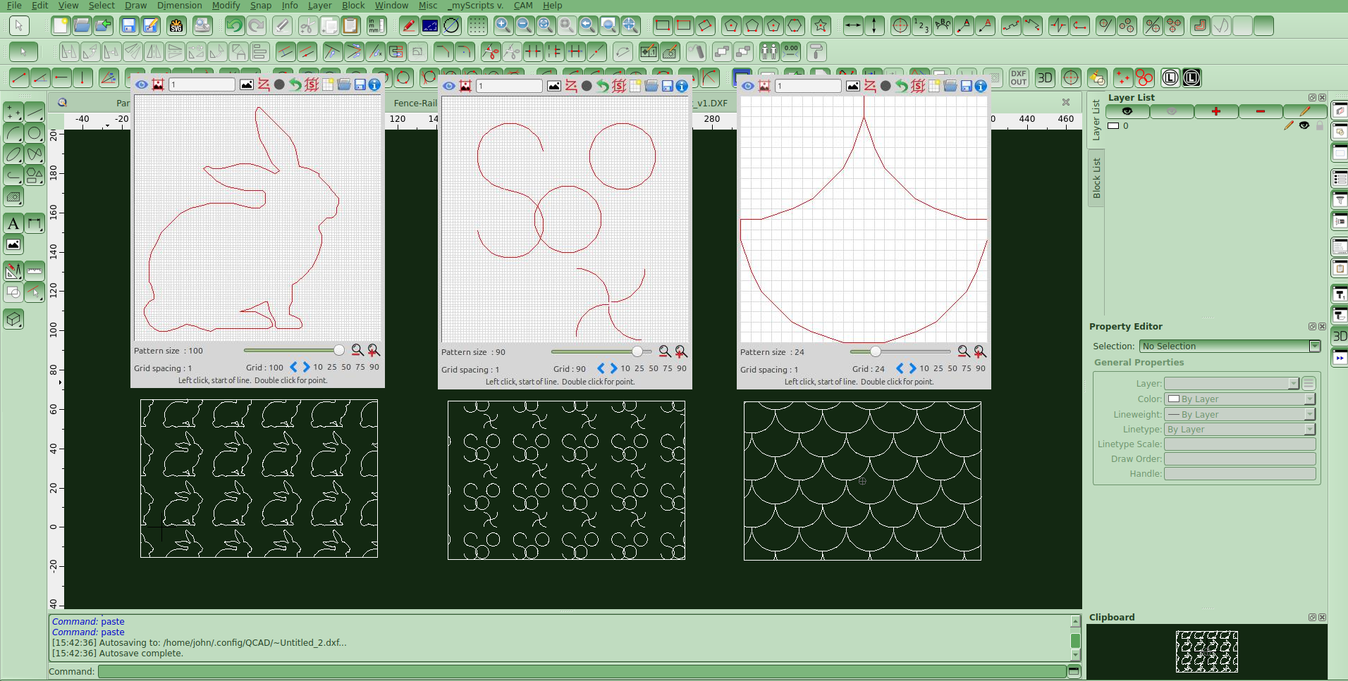
For ‘chervron my try’, probably chevrontest.pat, it seems to render 1 line alternating every 4 intended.

90,2,0,0,4,0,0
90,0,0,0,4,0,0
270,0,4,0,4,0,0 ; ==2
0,0,0,0,4,0,-4  ; Horizontal dotted lines
270,4,4,0,4,0,0 ; ==3
0,4,0,0,4,0,-4  ; Horizontal dotted lines ==4

Or 2 stacked out of 4, my guess is on those that are defined as downwards.
Probably where QCAD renders 3 stacked lines of all 4 XLines, 2 down and 2 upwards. :wink:
The dots are also 2 stacked dots each.
Such a pattern definition together with the 10 slanted definitions may slow down the rendering.

For this pattern I can’t replicate the missing link in the top left corner. :open_mouth:


Why not simple e_geek while it can be (over-)complicated … :exclamation:
This pattern can be broadly simplified to 3 definition lines and there is room to spare for a higher accuracy:

90,0,0,0,2
45,0,0,.7071067811865475,.7071067811865475,2.828427,-2.82842724949238
315,2,2,-.7071067811865475,.7071067811865475,2.828427,-2.82842724949238

Just add the repeated (singular) dots where you want them to occur, ideally on a horizontal definition as described above.

BTW: It doesn’t serve anything to create the same pattern in a different scale … A hatch can be created at any uniform scale.
Not all hatch patterns with slanted lines can easily be scaled non-uniform.
For this reason BPM is limited to certain strict ratios by developer choice.

Regards,
CVH

I’ve tried your .pat files in Qcad running in Linux, they all display correctly, including the preview. I’m wondering if it’s a software/hardware graphical glitch.

Yes they do Pete, under Windows too … In the above I assume they are not used under QCAD.

Then QCAD is hardened for the double dot in the line pattern.
The sum of all the dashes is zero long and it renders no pattern, aka an endless line. :wink:

Regards,
CVH

Thank you for all this information. I did indeed think that it could be transferred to any CAD software. Sorry if I misunderstood. Thank you again for your help.

It can … It should … I am not aware if this is specified. :wink:
All because the content of a *.pat file is based on the universal DXF standard.

Then:

90,2,0,0,4,0,0

Is not entirely correct according the standard.

Orientation of patterned lines = 90 degrees
Start of pattern on the line = (2.0, 0.0)
Offset to start for all next copies = +/-(0.0, 4.0)
Pattern: dash1 (zero=dot), dash2 (zero=dot), ... dash12

The pattern part itself is identical to a line type definition in a *.lin file excluding the prefix A = A-type alignment.
For hatch patterns, the internal alignment is fixed and not corrected automatically as with normal line-art.

Analog to no pattern definition at all for continuous lines, the pattern for an endless line should be , or left open.

90,2,0,0,4

Digging deeper:

  • For a pattern there must be at least two dash specifications.
    The first dash length value is 0 or greater (a dot or pen-down segment).
    The second dash length value should be less than 0 (a pen-up segment)
    .’

This doesn’t specifies that 2 is mandatory but in the case of any, the sum of dash lengths in absolute must at least be non-zero.

QCAD is (mostly) hardened against possible dubious situations or actions are taken in the case they occur or are reported.
No pattern = Empty dash list OR Zero total length to repeat, it would take forever to repeat nothing over some finite length.
QCAD even allows the first dash to be a ‘pen-up segment’ or two successive ‘pen-up/down segments’ and so on.

Regards,
CVH

Hi All,

First off, a big thanks to ELLE_Sonny for supplying the screenshots from AutoCAD.

Pete and I have decided to add AutoCAD compatibility in the next release of our software. Currently, our software is fully operational in QCAD and displays patterns without any errors whatsoever.

Just to clarify:

Our software does not claim to optimise hatch pattern files.

For example, an optimised chevron pattern could indeed be written using just 3 lines, but you would need to understand the .pat code to do this.

Our software is WYSIWYG (What You See Is What You Get), very easy to use, and does not require any programming knowledge.

Key Points:

QCAD is not AutoCAD, and AutoCAD is not QCAD.

There are subtle differences between CAD platforms, especially when it comes to handling .pat files.

Below is a quick overview of how some popular CAD packages handle .pat files:

1. AutoCAD (.pat files)

AutoCAD is the most common CAD software that uses .pat files, primarily for defining hatch patterns.

Structure: AutoCAD .pat files are plain text files that contain a series of lines. AutoCAD interprets these lines as repeating patterns.

Custom Patterns: Users can create or modify their own .pat files using a text editor, and AutoCAD will interpret these patterns when applied to a hatch.

Format: The .pat file format is specific to AutoCAD, but other programs may use a similar structure for compatibility.

2. SolidWorks (.pat files)

SolidWorks uses a different system for patterns and does not directly use .pat files.

Hatching and Patterns: SolidWorks uses its own pattern system, typically with predefined pattern libraries. However, it is possible to import some AutoCAD hatch patterns by converting them or using third-party tools.

3. Revit (.pat files)

Revit uses .pat files in a similar way to AutoCAD, but the files must be formatted in a way that Revit can interpret.

Compatibility: Revit supports importing AutoCAD .pat files, but you may need to adjust the scale or other properties for the pattern to display correctly.

4. MicroStation (.pat files)

MicroStation also supports hatch patterns but does not use .pat files in the same way AutoCAD does.

Patterning: MicroStation uses .cel files (cell libraries) and other pattern definitions, which are not always compatible with AutoCAD .pat files out of the box.

5. SketchUp (.pat files)

SketchUp does not natively support .pat files.

However, SketchUp has its own mechanism for creating fill patterns for materials, and it can import CAD files (including AutoCAD .dwg and .dxf files) that may contain patterns defined in .pat files.

Are There Shared Standards?

While .pat files often share the same name across different CAD systems, each CAD platform has its own interpretation or extension of the format.

The basic structure of the .pat file is often similar across systems like AutoCAD and Revit, but there may be slight differences in how they handle things like scale, angle, and other properties.

Can You Use One CAD Package’s Patterns in Another?

It is possible to import or convert .pat files from one CAD system to another, but this typically requires some conversion or reformatting (either manually or using conversion software).

AutoCAD and Revit are generally compatible with the same basic pattern structure, but other platforms like MicroStation or SolidWorks may not interpret them correctly without adjustments.

Conclusion

There is no absolute “standard” for .pat files, though AutoCAD and Revit have a more consistent structure.

Other programs may require conversion tools or manual adjustments to use .pat files properly.

If you’re working across different CAD platforms, it’s important to consult the specific software’s documentation on hatch patterns or .pat file support and conversion.

I’ll be uploading the next versions within the next few days.
Linux variants will be first, followed by Windows, which is very problematic at the moment due to SmartScreen warnings.

Happy Hatching,
John & Pete

To set the record straight, I was not referring to some universal pattern file standard but to the universal DXF standard.

Referring to the AcDbHatch specification and the pattern data that comes after group code 78, see Pattern Data (DXF) specification.
The only difference with the content of a *.pat file is group code 79 that specifies how many dash values with group code 49 to read as dash list.
Coming from a *.pat file, each definition is read to the end of the line.

For a DXF to be compatible, all other programs must use this structure for importing or exporting DXF data.
The content of a *.pat file is to initially create a patterned Hatch by the application.
Not to recreate a patterned Hatch from DXF data.

How native patterns files or linetypes definitions are structured is purely native to the application, QCAD uses the ACAD structure.
Basically not inventing the wheel twice.
The same is true for the drawing format, native is not per definition DXF or DWG.
Most obvious that you can compile a list of differences.

The ‘dot, dot and nothing else’ flaw doesn’t originate from a difference between QCAD and ACAD.
The DXF created with such pattern lists 79:2 49:0 49:0 what is bogus, 79:1 49:0 is the same sort of flaw.
In-line repetition distance is every zero units further and backwards along the line up to an intersection with a boundary segment.
Any finite length divided by zero results in an infinite number of repetitions.
But typically the result of such an equation results in NaN … Not a Number … A division by zero error.
The difference between QCAD and ACAD is how such a situation is handle.


You don’t need an in-depth knowledge of pattern coding to come up with the optimized chevron pattern.
It is a pattern defined in a ‘Tile’ or rectangular area of 4 by 1 units high and repeated orthogonal in all 4 directions.
Then BPM is limited to squared definition areas.
Logically a dash or dot is inside the definition area but it is also valid if it extends to outside the area and even when fully outside.
A simple matter of identifying the first in-line repetition and the first left or right parallel copy or clone.

  • Vertical lines are rather straight forward, these repeat in parallel every 2 units, endless lines and thus no dash pattern.
    The pen-down is the 45°(315°) diagonal of 2 by 2 and is sqrt(2^2+2^2) = sqrt(8) or 2.82842712474619… long, repeats in-line every 4 by 4.
    The offset to the next parallel is the diagonal of 0.5 by 0.5 and is sqrt(0.5) or 0.7071067811865475…, the shift is also sqrt(0.5).
    Offset and shift values their sign depends on forward or backward and on left or right.
    Why 315°for the second? It is a choice so that segments connect at (2, 2), starting at (0, 4) in the 135° direction is the other option.

At best we include all values in full floating point notation (15-16 significant digits) but you may run out of text space when limited.
We can truncate the length of the pen-down part to (+)2.828427 (±1ppm) what is textually shorter.
But the sum of the dashes in absolute must be 2 times sqrt(8) to repeat every 4 by 4 :exclamation:
Hence, pen-up is (-)2.8284272494923801 with 17 significant digits, the 01 at the end won’t matter anymore using 15-16 digits.

Regards,
CVH


BPM-Sketches - 22-11-25.zip (978 KB)
BPM - V1.5.1 - Linux 32bit Deb.zip (1.79 MB)
BPM - V1.5.1 - Linux 64bit AppImage.zip (3.12 MB)
BPM - V1.5.1- Linux 64bit Deb.zip (1.84 MB)
BPM - V1.5.1 - Linux i386 AppImage.zip (2.98 MB)
BPM - V1.5.1 - Setup - 64bit - Windows.zip (2.71 MB)
BPM - V1.5.1 - Setup - 32bit - Windows.zip (2.59 MB)
Windows 64-bit and 32-bit versions have now both been updated.
The previous installers weren’t creating the INI file on first run, which caused an error message the first time the app started.
The error was harmless — the INI file was created after first use — but both installers have now been rebuilt so the setup process is smooth and error-free.

Happy Hatching :smiley:
John & PeteVick