Hello!
I am evaluating qcad professional for linux. For now I am exploring command line tools : dwg2pdf and dwg2bmp to convert dxf files (AC1009) to pdf/png
info:
Linux Red Hat 5.14.0-427.28.1.el9_4.x86_64
QCAD version 3.31.2
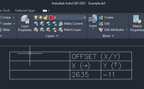
dwg2pdf: I was able to get what I need, but there is an issue with display and print to pdf of arrow symbols. See attachments. In Autocad arrows are displayed correctly centered within parenthesis but in qcad and pdf output are shifted.
dwg2bmp: I have already searched in the forum but it still not clear how to set properly the resolution : the target is to obtain a 100 DPI png file. I have the feeling that if he image is too large it wont’ be generated as per resolution set in the command so it has to be scaled. Is it correct?
On arrows, please include the DXF example so that we can replicate the issue.
Regarding dwg2bmp, the r switch indicates the resolution in pixels per drawing unit. -r 100 sets that to 100px/unit.
I can’t find an example in the nature of -r100x100.
Depending the drawing unit that is 100px/inch = 100 dpi, 100px/mm = 2540dpi, 100px/foot = 8.333 dpi, and so on.
The reference indicates that the maximum size for the output file is 536’870’911 pixels, or for example 23’170x23’170 pixels.
In 100px/unit that is 231.7 by 231.7 units.
The text with the arrows consists of text “X ( )” and lines that draw the arrow. Since the fonts between Autocad and QCAD don’t match, this will never line up exactly.
I’d recommend to make the arrow part of the text instead, using the appropriate Unicode symbols: