When i am using anti aliasing view all the fittings looks in one piece but the view is very faded. The screen is not bright enough. When I am using Screen based Linetypes (NL) the screen brightness is perfect but i cannot see the blocks in one piece (they are dashed). So how can I solve this screen brightness problem?
I can not reproduce this.
On my monitor both Normal and Screen-Based in Model Space looks OK.
There are a few minor differences noticeable.
In fact there is not much to render faded while the thousands of polylines all have a rather large custom Width.
Didn’t even attempt to view them in Paper Space!
Define ‘view’.
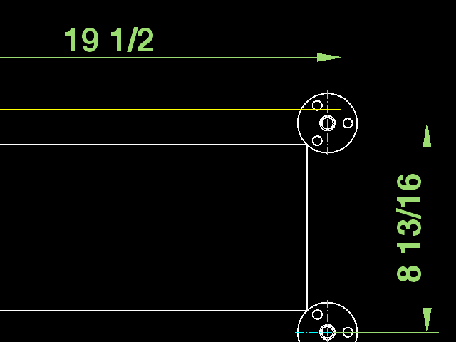
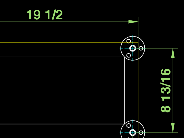
Explain ‘dashed’ :
‘dashed’ as represented as dashed lines.
Or
‘dashed’ as everything is segmented …
… That’s what you get when you represent a circle with line segments.
But far worse is the use of a huge amount of tiny segments for simple straight lines.
I reported:
Fully at random:
F-0-1 (4 lines) are 77 polylines
F-1-0 (squared light fixture?) are 799 polylines
W-85-0 (a simple door: 4 lines + 1 arc) are 64 polylines
GFF-16-6 (4 circles) are 255 polylines
Hardly noticeable … the two PNG files have about the same brightness on my monitor.
When I catch the pixel colors, they are the same.
Anti Aliasing is somewhat less pixelated.
To do so, adjacent pixels have a shaded color.
I don’t have those in standard view.
These are artifacts of segments touching and the use of Anti Aliasing.
(Edit Block, select two in-line segments)
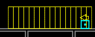
My point exactly, the shown yellow staircase with arrow consists of 915 Polylines.
The inner ‘spokes’ are 12 Polylines each, Width 3mm and doubled at 1.6474938 apart.
That are 24 Polylines every ‘spoke’.
E.g.
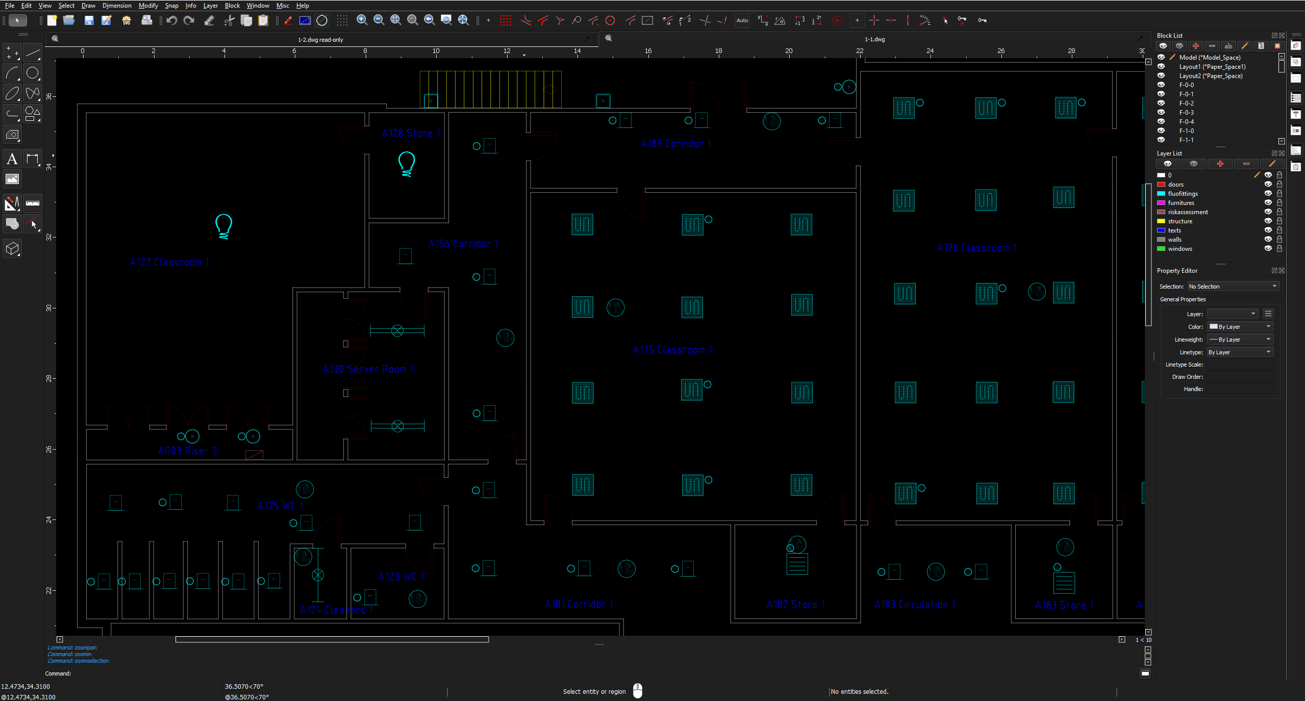
Layer ‘fluofittings’, 397 Block References, explode to 199,205 Polylines with various widths.
(Can’t do it in one go as QCAD will crash eventually)
There are only 14 different types of pictograms used for ‘fluofittings’.
But, every Block References has its own definition.
The file comes as a DWG of 5.14Mbyte.
Once altered a single piece, I have a DXF backup file of 50Mbyte.
What swiftly exceeds the 100Mbyte.
In short: unworkable.
I assume ‘fkirim’ isn’t reading these posts anymore.
He was in a hurry to get a quick fix.
Andrew proposed a refund.
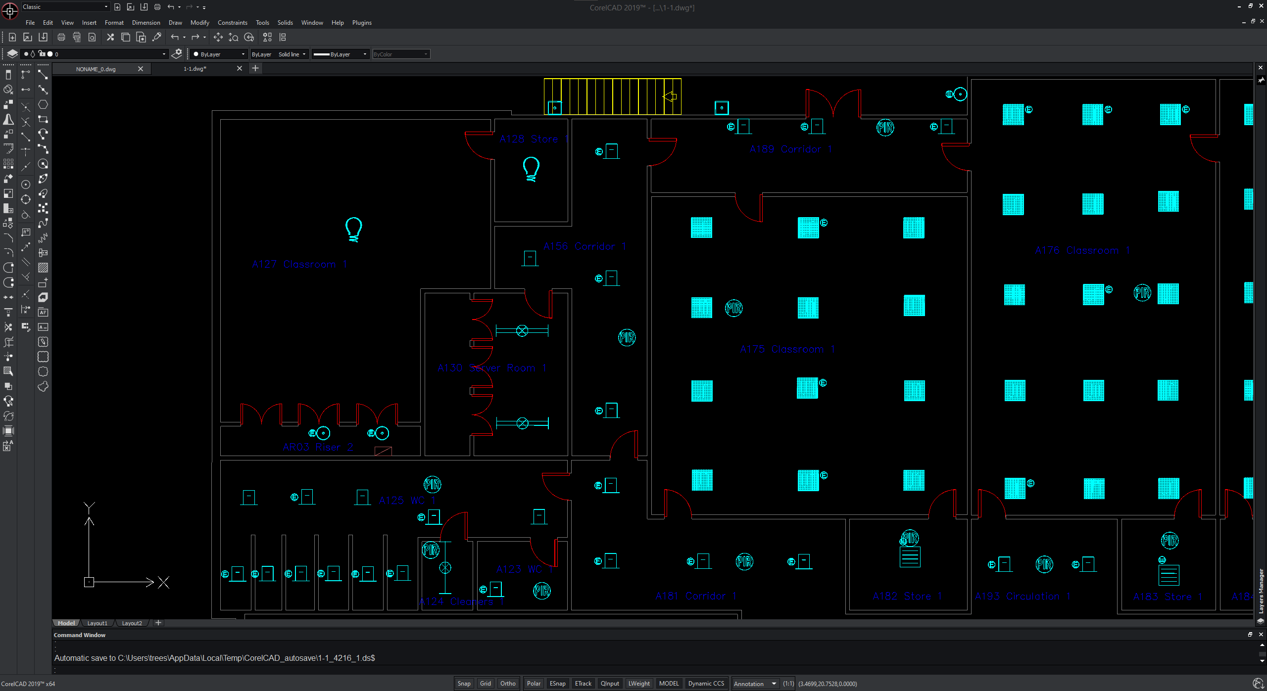
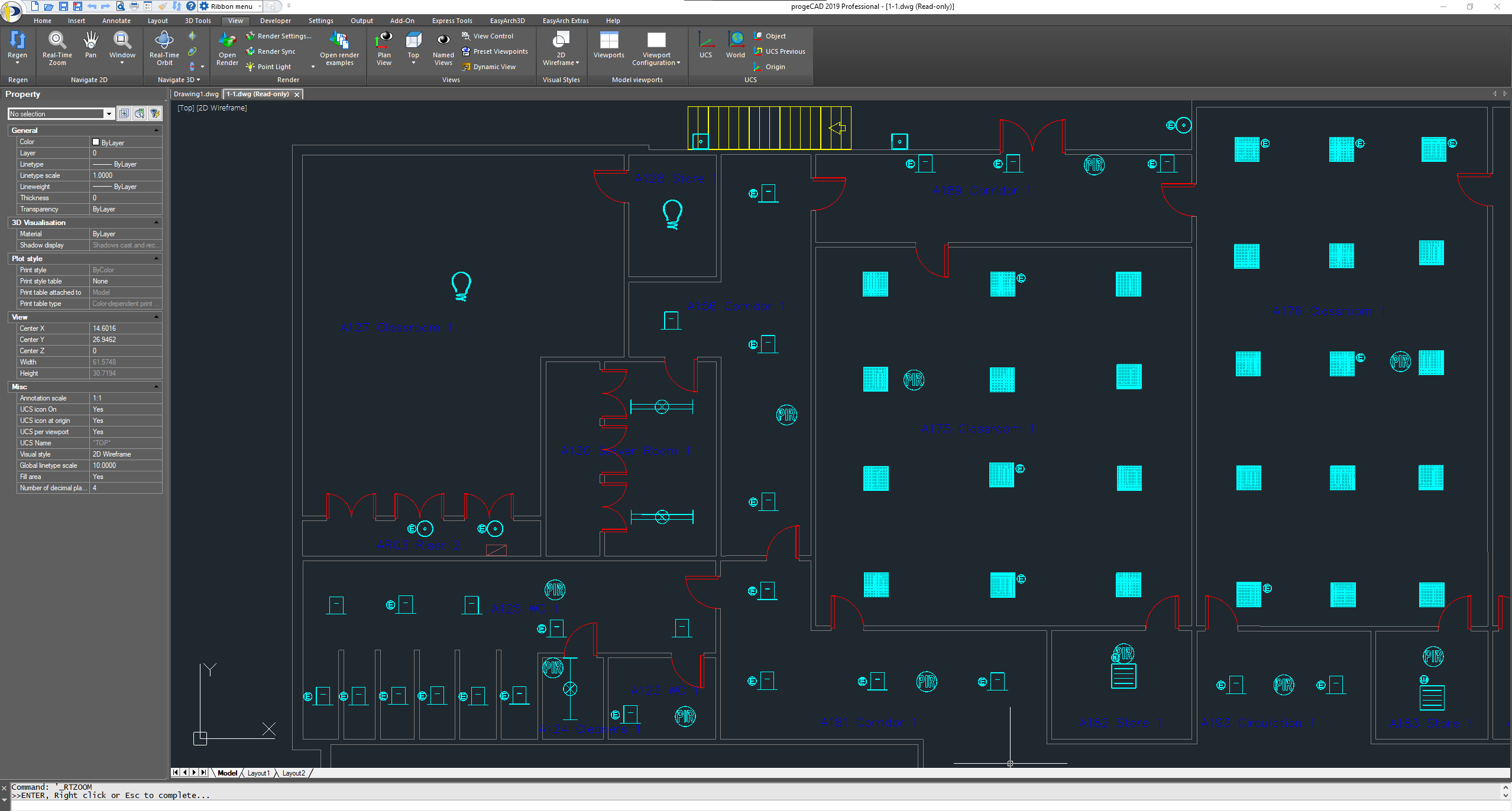
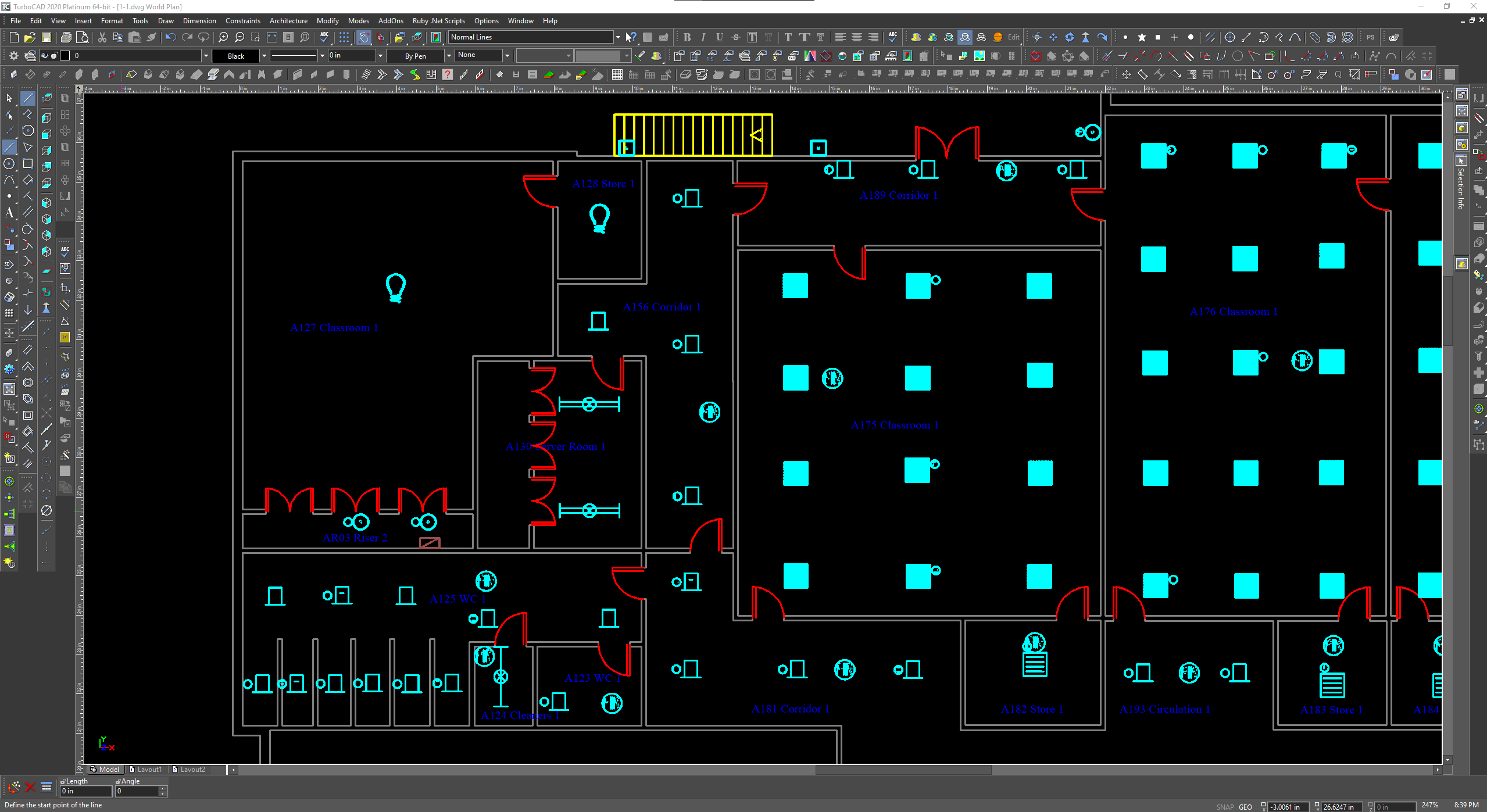
I opened the file. Looking at the drawing i had to laugh as the doors could never open more than 90 degrees. Also why so many polylines? e_confused Bad drawing. Irregardless the only way i get display fading is turning Screen-Based Linetypes on and off. This causes the wall thickness to increase causing the screen to be much brighter. Anti-Aliasing works as should, no display fading. I do notice that the doors are very faint red. Just for fun i opened the drawing with 3 other different Expensive CAD programs on my work computer. QCAD looks quite nice don’t you think The CAD file is truly crazy and i would not accept it in a business case.
All the polylines use a custom width and QCAD renders those differently as Screen-Based or not.
Screen-Based can be best seen as ‘Trying to display what it would look like on paper’.
Paper is easily 300dpi and up. Never came across a 1200dpi screen yet.
Seems to be true in a 2558x1375 screen grab. On a 1920x1080 screen they are bright red.
Here the screen looks more as the TurboCAD example.
Wow, you really got place to spare for the List widgets
That was our point exactly, but the guy kept coming back with that QCAD should solve his issues in a hurry, in a click.
He never provided the origin of the file, nor what application.
Here is a test i did mainly to learn how to upload animations to this Forum. I used FFmpeg to create the GIF in High Quality.(ffmpeg -i input.mkv -vf “fps=10,scale=0:-1:flags=lanczos,split[s0][s1];[s0]palettegen[p];[s1][p]paletteuse” -loop 0 output.gif) I created a 5 polyline door beside the 64 polyline block door on the door layer in the drawing. This is on a 1080 screen. Nobody would typically draw a 64 polyline door but maybe a 64 polyline block. So it seems the more polylines in view at a time the more QCAD has troubles rendering to screen. At least with small short polylines. I also tried different colours with same results.
To Answer the OP Question of Why do my Blocks look Dashed? Your Blocks are made with lots of little PolyLines (not ideal drawing practice) with a Global Width of 0.03937008" Change Global Width to 0" to inherit the Layer LineWeight properties and the problem of “Dashed Lines” is resolved. I’m showing 1 Block Exploded for proof of concept as original drawing has many identical but individual Blocks e_confused